


Table of contents: Removal ↓ Installation ↓
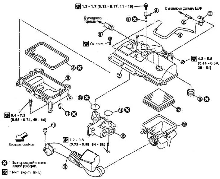
1. EVAP carbon canister purge solenoid valve; 2. Vacuum hose; 3. Vacuum hose; 4. Manifold Absolute Pressure Sensor; 5. O-ring seal; 6. Vacuum hose; 7. Air cleaner housing (upper); 8. Gasket; 9. Air cleaner housing (lower); 10. Gasket; 11. Clamp; 12. Air duct; 13. Gasket; 14. Gasket; 15. Electric throttle actuator; 16. Air cleaner housing; 17. Air cleaner filter element; 18. Gasket
Removal
Note: PP 1-2 can be skipped and you can go straight to 3 (disconnecting electrical wiring and hoses, etc. cannot be missed)
1. Disconnect the connector and remove the manifold absolute pressure sensor.
Attention:
- Handle the MAP sensor with care. Avoid impact.
- Do not allow foreign materials to come into contact with the sensor (oils, chemicals, etc.).
2. Disconnect the connector and vacuum hose and remove the EVAP canister purge solenoid valve.
Caution: Handle the EVAP canister purge solenoid valve with care. Avoid impact.
3. Remove the air duct. Remove the clamps and, after turning the air duct (2) by approximately 90°, remove it from the air cleaner housing (1).
Information copied from the website: NissanBook.ru
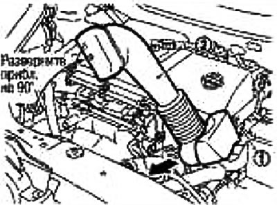
4. Remove the clamps, tilt the air cleaner housing downwards, then swing it forward and remove the air cleaner housing and air cleaner filter element.
Note: Removing and disassembling the air cleaner housing (upper and lower) are described below.
5. Move the transmission breather hose.
6. Remove the air cleaner housing assembly as follows:
- Under the air cleaner housing (upper and lower) refers to the air cleaner housing assembly.
- a. Disconnect the electrical connector from the electric throttle actuator.
- b. Disconnect the vacuum hose from the brake booster.
- c. Loosen the bolts in the reverse order to that shown in the figure
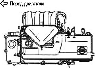
7. Remove the air cleaner housing assembly by lifting it up.
Apply slow and even pressure to the joint at the top of the intake manifold while lifting and remove the air cleaner housing assembly.
Attention:
- To avoid damaging components, do not make sudden movements.
- To prevent foreign particles from entering when removing the air cleaner housing assembly, seal the openings in the top of the intake manifold with tape.
8. Loosen the bolts in the reverse order shown in the figure and separate the upper air cleaner housing from the lower one.
9. Remove the throttle actuator from the upper air cleaner housing.
Turn the upper housing of the air cleaner over onto a sheet of protective material to avoid scratching its surface.
Handle the electric throttle actuator with care and do not make adjustments.
Installation
1. Install the throttle actuator (1) to the upper air cleaner housing (2) as follows:
- a. Insert the gasket (3) into the base of the coupling.
- b. Insert the gasket (4) into the outer groove of the throttle valve hole on the side of the upper air cleaner housing (2).
- c. Install the electric throttle actuator.
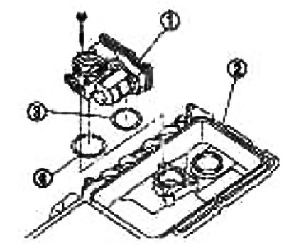
There is no specific order for tightening the mounting bolts.
If the connector is disconnected from the electric throttle actuator, perform "Closed Throttle Position Learning". See chapter Engine management system.
If the throttle actuator is replaced, perform "Learning the air supply at idle speed" and "Learning the closed position of the throttle valve". See chapter Engine management system.
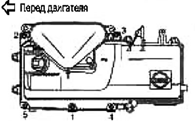
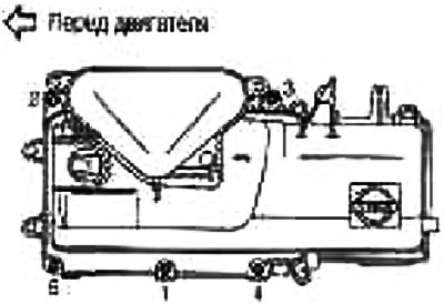
2. Connect the upper air cleaner housing to the lower one.
Tighten the bolts evenly in two passes in the order shown by the numbers in the illustration.
1st pass: 1.9-2.2 Nm (0.20-0.22 kg·m)
2nd pass: 3.8-4.4 Nm (0.40-0.44 kg·m)
3. Install the air cleaner housing assembly as follows:
- a. Insert gaskets into the upper part of the intake manifold (1) and PCV channel (2).
- Insert the gaskets into the top of the intake manifold so that the protrusion on the housing (4) fits into the recess (3) on the side of the gasket.
- Make sure that no foreign particles come into contact with the gasket or sealing area.
- b. Insert the air cleaner housing assembly into the upper portion of the intake manifold.
- At the same time, insert the lower channel tabs into the PCV channel holes on the valve cover.
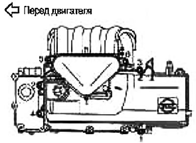
- c. Tighten the bolts in the order shown by the numbers in the figure.
- Tighten the bolts evenly in several passes
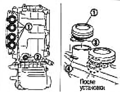
Note: To prevent the gaskets from bending or twisting, insert them straight and at a right angle.
Caution: Tighten after making sure that bolts 5 and 6 are correctly inserted into their places.
4. Install the air cleaner housing and air cleaner filter element. See "Replacing the Air Cleaner Filter Element" below.
5. Install the air duct.
6. Install the EVAP canister purge solenoid valve.
7. Install the manifold absolute pressure sensor.
Make sure that no foreign particles enter the flange, O-ring or mounting hole.
Tighten the mounting bolt, making sure the sensor is fully seated in the mounting hole.