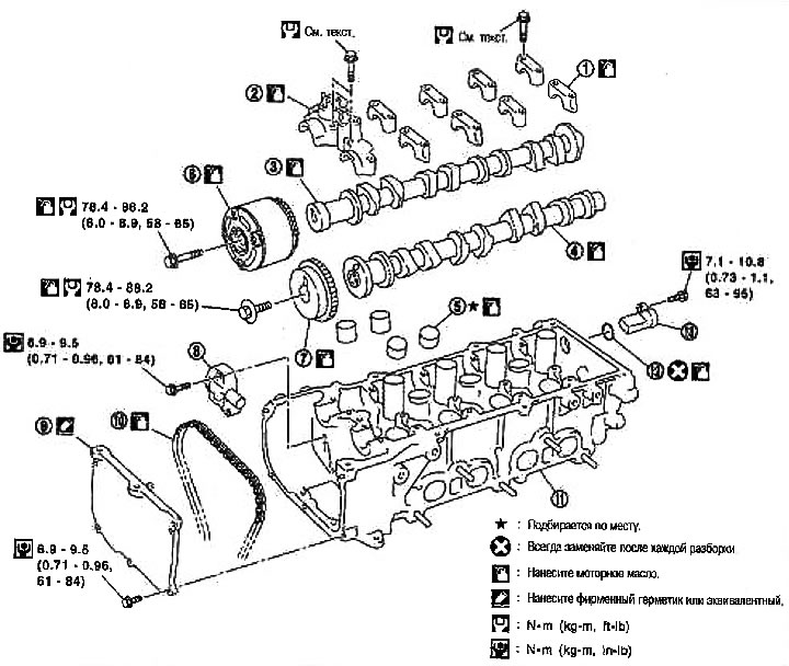
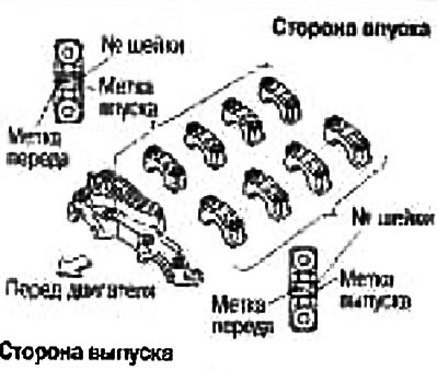
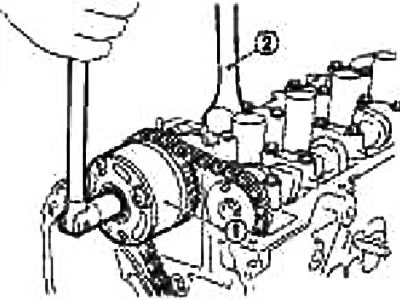
1. Brackets (№№2-5) camshafts; 2. Bracket No. 1 camshafts; 3. Camshaft (inlet); 4. Camshaft (release); 5. Valve lifter; 6. Camshaft sprocket (inlet); 7. Camshaft sprocket (release); 8. Timing chain tensioner; 9. Front cylinder head cover; 10. Timing chain; 11. Cylinder head; 12. Camshaft angle sensor (PHASE)
Removing
1. Remove the protective pad from the front right fender.
2. Fix the engine in one of the following ways. Remove right engine mount and engine mount bracket (upper). See section «Removal and installation».
Install the lifting eyelets on the engine and hook with the winch. See section «Removal and installation».
Support the bottom of the oil pan with a jack, safety stand, etc.
3. Remove the valve cover. See above section «Valve lid».
4. If necessary, remove the camshaft angle sensor (PHASE) on the back of the cylinder head.
Attention:
- Handle the deliverer with care, do not drop or hit it.
- Avoid getting metal powder on the magnetic part of the probe tip. Do not leave sensors where they may be affected by magnetism.
5. Remove the right headlight. See chapter electrical equipment.
6. Remove the front cylinder head cover.
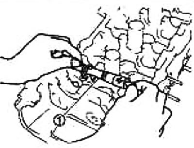
7. Set the piston of cylinder No. 1 to TDC on the compression stroke by performing the following operations.
- A. Turn the crankshaft pulley clockwise.
- b. Make sure the lobes on the intake and exhaust camshafts of cylinder #1 are facing outwards,
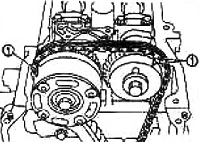
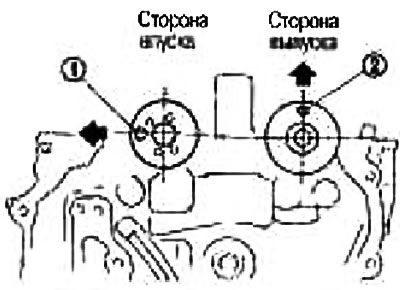
- With. Make sure the sync labels (1), knocked out on the sprockets of the intake and exhaust camshafts, have risen as shown in the figure.
- Otherwise, turn the crankshaft pulley one more turn and align the marks as shown in the figure.
- d. Make sure the timing marks stamped on the intake and exhaust camshaft sprockets line up as shown, then paint the timing marks on the timing chain links.
- e. Make sure the intake camshaft sprocket is in the maximum advanced position.
Attention:
- Removal and installation of the intake camshaft sprocket is required to maintain the maximum advance position for the following reasons. Therefore, follow the procedure exactly as indicated below.
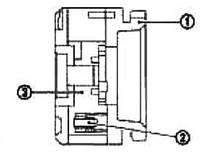
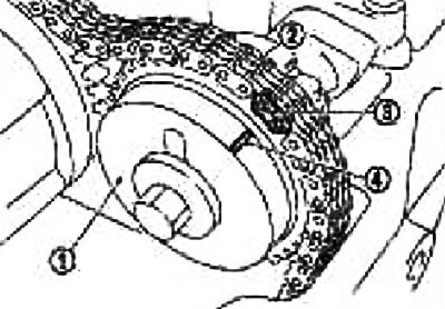
- On this model, a design is used in which the sprocket (1) and blade (at the junction of the camshaft) (3) rotate and move relative to each other at some given angles.
- When the engine stops, the blade (3) is in the position of maximum delay. It does not rotate because it is locked in the sprocket by an internal locking pin (2).
- If you turn the camshaft sprocket mounting bolts under the specified conditions (in the position of maximum delay), then apply a transverse load (shear force) to lock pin (2). This will damage the lock pin (2) and malfunction of the mechanism.
Set the intake camshaft sprocket to the maximum advanced position as follows:
Caution: Do not remove the chain tensioner before performing this operation.
Note: «Direction of rotation» indicates the direction of rotation as viewed from the front of the engine.
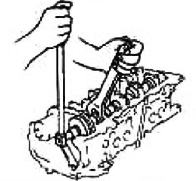
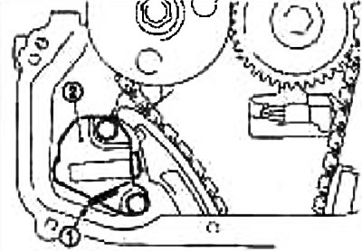
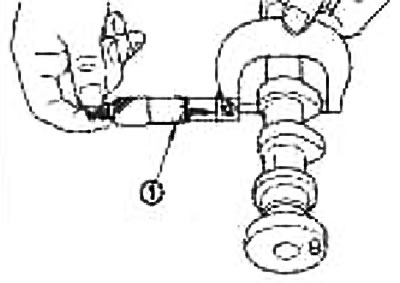
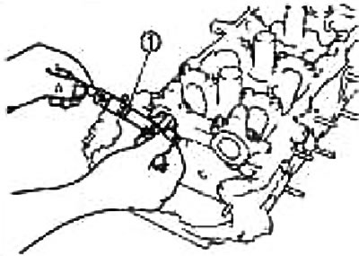
- A. Lock the hex part with an adjustable wrench (1) so that the intake camshaft does not rotate.
- b. With the help of an air gun (2) apply pressure to the lubrication channel of the intake valve timing mechanism from the advance side on top of the bracket No. 1 of the camshafts (1).
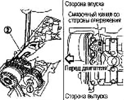
Air pressure: 300 kPa (3.06 kg/cm2) or more
Note: The locking pin is held in the unlocked position by compressed air.
Maintain pressure until the end of the paragraph «e».
Attention:
- Do not damage the lubrication channel with the tip of the gun.
- Before applying compressed air, carefully wipe off the oil from the top of the #1 camshaft bracket. When applying pressure, cover the area adjacent to the gun with a cloth. Wear protective goggles if necessary.
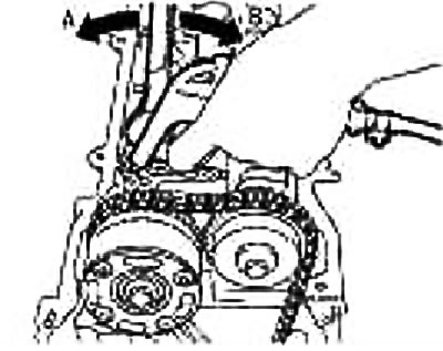
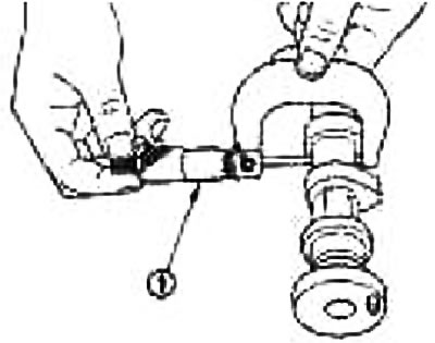
- With. Slowly turn the intake camshaft counterclockwise in the direction «A» (toward the top of the intake manifold).
Carry out the operation with compressed air.
Attention: Do not allow the key holding the camshaft to move.
- d. During the above operation. You will hear a clicking sound from inside the intake camshaft sprocket (sound indicating the disengagement of the internal locking pin). When you hear this sound, slowly rotate the intake camshaft in the opposite direction «IN» (clockwise: towards the exhaust manifold) and set to the maximum advance position.
Carry out the operation with compressed air.
If the blade part (at the junction of the camshaft) rotates one relative to the sprocket, then the locking pin is disengaged, even if the click is not heard.
If the locking pin does not disengage, lightly shake the camshaft with a wrench.
If the lock pin is still tight after performing the above operation, lightly tap the front end of the intake camshaft with a plastic mallet.
- e. As soon as the vane begins to rotate by itself, and then, when the camshaft is turned, the sprocket also begins to rotate, the maximum advance position has been reached. When the specified state is reached, the operation is completed.
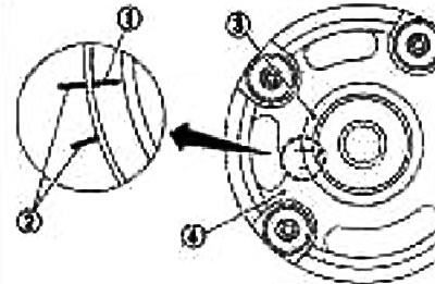
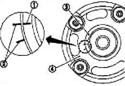
Make sure the label (1) the position of the maximum advance of the mechanism for regulating the valve timing of the intake valves on the blades (3) and alignment mark (2) on an asterisk (4) stand up as shown in the picture.
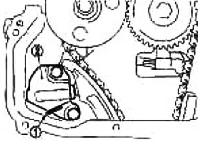
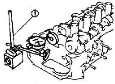
9. Lock the plunger in the fully compressed position by inserting the lock pin (1), e.g. a paper clip and remove the chain tensioner (2).
10. Holding the camshaft by the hex part with an adjustable wrench, loosen the fixing bolts and remove the intake and exhaust camshaft sprockets.
Attention:
- Make sure that the tool does not touch the air conditioner pipes.
- Do not loosen the fixing bolts by fixing the camshaft in areas other than the hex part, or by tightening the timing chain.
Note: With the front cover installed, the timing chain and crankshaft sprocket will not come off, so there is no need to maintain chain tension.
When removing/installing the intake camshaft sprocket, observe the following precautions:
Attention:
- Secure the blade with vinyl tape to prevent the blade from turning so that the lock pin does not engage in the maximum retard position.
- Handle the camshaft sprocket with care, do not strike it or drop it.
- Don't disassemble the asterisk. (Do not loosen the four bolts on the front face).
If, during removal, the locking pin is engaged in the maximum lag position, restore the original position as follows:
- A. Install the intake camshaft sprocket back onto the camshaft and tighten the mounting bolts until there is no air leak.
Caution: To avoid damage to the internal locking pin, the tightening torque of the mounting bolts must be kept to a minimum.
- b. Apply compressed air, disengage the locking pin as in step 8 and rotate the blade to the maximum advanced position (This operation can be performed with the timing chain removed).
- With. Remove the sprocket from the camshaft.
11. Remove the camshaft brackets.
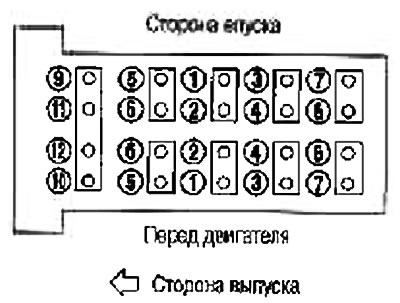
Loosen the bolts in several passes in the reverse order shown in the figure
12. Remove camshafts.
Caution: Be careful not to damage the signal disc on the rear end of the intake camshaft.
13. Remove the valve lifters.
Mark the locations and stack the components in order without mixing them.
Installation
1. Install the valve lifters.
Install them in the same places in which they were before removal.
2. Install the camshafts.
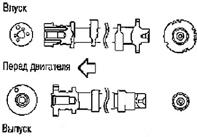
The intake and exhaust camshafts can be distinguished by the shape of the front and rear ends.
3. Install the camshaft brackets.
Completely remove any debris from the underside of the camshaft brackets and upper surfaces of the cylinder head.
Install the camshaft brackets in the same places and in the same direction as before removal, referring to the markings stamped on the top surface.
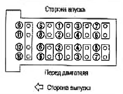
4. Tighten the camshaft bracket bolts as follows:
- A. The bolts have different sizes depending on the installation location:
Bolt color: 1-10: black; 11.12: golden;
- b.Tighten in order 9 to 12 first, then in order 1 to 8. Torque: 2.0 Nm (0.2 kg m)
- With. Tighten all bolts in the order indicated by the numbers in the figure. Tightening torque: 5.9 Nm (0.6 kg m)
- d. Re-tighten all bolts in the order indicated by the numbers in the figure. Tightening torque: 9.0-11.8 Nm (0.92-1.2 kg m)
5. Install the intake camshaft sprocket as follows:
Make sure the label (1) the position of the maximum advance of the mechanism for regulating the valve timing of the intake valves on the blades (3) and alignment mark (2) on an asterisk (4) stand up as shown in the picture.
- A. Put on the timing chain (2), aligning the label (3) (applied to it upon removal) labeled (4) on the camshaft sprocket (1).
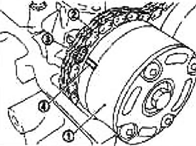
Align the dowel pin on the back of the sprocket with the pin hole on the camshaft, then fit.
- b. Fixing the camshaft by the hex part with an adjustable wrench (2), tighten the intake camshaft sprocket fixing bolt (1).
- With. Remove the tape from the camshaft sprocket.
6. Install exhaust camshaft sprocket (1) in the following way:
- A. Put on the timing chain (2), aligning the label (3) (applied to it upon removal) Tagged (4) on the camshaft sprocket (1).
Align the locating pin on the front surface of the camshaft with the pin groove on the camshaft sprocket, then fit.
- b. Using an adjustable wrench, secure the camshaft by the hex portion and tighten the exhaust camshaft sprocket mounting bolt.
- With. Make sure the marks on the intake and exhaust camshaft sprockets line up with the marks on the timing chain.
7. Install chain tensioner (2).
Secure plunger with pin (1).
After installation, remove the locking pin (1) and release the plunger.
Check again that the marks on the intake and exhaust camshaft sprockets are aligned with the marks on the timing chain.
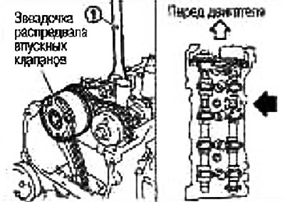
8. Slowly turn the crankshaft pulley (1) clockwise and set the intake camshaft sprocket to the maximum retard position.
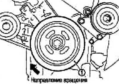
When the crankshaft rotates for the first time, the sprocket begins to rotate. Continue to rotate the crankshaft until the blade also rotates (camshaft), the position of maximum delay has been reached.
By slightly turning the crankshaft counterclockwise, you can verify that the lock pin is engaged by seeing the blade and sprocket rotate together.
9. Establish a forward cover of a head of cylinders.
Apply the sealant evenly to the places indicated in the figure. Use branded sealant or equivalent.
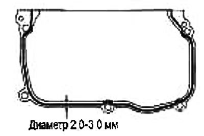
Install so that the front cover of the cylinder head is aligned with the locating pin on the side of the cylinder head.
10. Install the camshaft angle sensor (PHASE).
Make sure the flange, o-ring or mounting hole is free of foreign matter.
Tighten the mounting bolt making sure the sensor is fully seated in the mounting hole.
11. Check and adjust valve clearances. See section «valve clearances».
12. After this operation, installation is carried out in the reverse order of removal.
Check after removal
Camshaft runout
Install the camshaft on two prisms with journals #2 and #5.
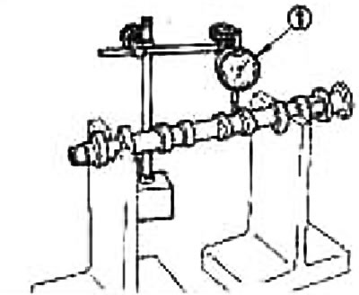
Attention: Do not install the camshaft on prisms with neck No. 1 (from the camshaft sprocket side), because its diameter differs from the other four.
Attach the sensitive indicator head (1) vertically on neck #3.
Turn the camshaft by hand in one direction and measure the runout with a dial gauge (maximum indicator reading).
Limit: 0.04 mm or less.
If the runout exceeds the limit, replace the camshaft.
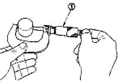
Camshaft lobe height
Measure the camshaft lobe height with a micrometer (1).
Standard Cam Height:
| CR14DE engine | |
| Inlet | 40.359-40.549 mm |
| Release | 39.743-39.933 mm |
If the height is out of specification, replace the camshaft.
Gap in the camshaft
Camshaft journal outer diameter
Measure the outer diameter of the camshaft journal with a micrometer (1)
| Standard | №1 | 27.935-27.955 mm |
| №№ 2-5 | 23.450-23.470 mm |
Camshaft bracket inner diameter
Tighten the camshaft bracket bolts to the correct torque.
Measure the inside diameter of the camshaft bracket with a bore gauge (1)
| Standard | №1 | 28.000-28.021 mm |
| №№ 2-5 | 23.500-23.525 mm |
Calculation of the clearance in the camshaft journals
(Gap in necks) = (camshaft bracket inner diameter) - (camshaft journal outer diameter)
| Standard | №1 | 0.045-0.086mm |
| №№ 2-5 | 0.030-0.071 mm |
If the reading is out of specification, replace either the camshaft or cylinder head, or both.
Note: The camshaft brackets are one piece with the cylinder head. Replace the cylinder head assembly.
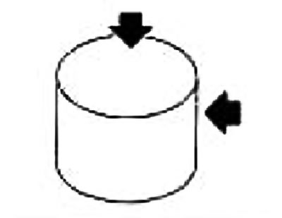
Camshaft end play
Install indicator (1) in the axial direction with a sensitive head to the front end of the camshaft. Measure the end play by moving the camshaft forward/back (axially).
Standard: 0.070-0.143 mm.
If end play is abnormal, replace camshaft and recheck.
If it again differs from the norm, replace the cylinder head.
Camshaft sprocket runout
Install the camshaft on two prisms with journals #2 and #5.
Measure the runout of the camshaft sprocket with an indicator.
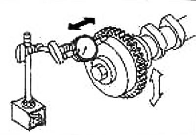
| limit | Inlet | 0.20 mm |
| Release | 0.015 mm |
If the runout exceeds the limit, replace the camshaft sprocket.
Valve tappet
Check for wear or chips on the surface of the valve lifter.
If any defects are found, replace the valve tappet.
Valve lifter clearance
Valve lifter outside diameter
Measure the outer diameter with a micrometer (1)
Standard: 29.960-29.975 mm.
Valve tappet hole diameter
Measure the diameter of the tappet bore in the cylinder head with a bore gauge (1).
Standard: 30.000-30.021 mm
Valve lifter clearance calculation
(Valve lifter clearance) = (tappet hole diameter) - (valve lifter outside diameter).
Standard: 0.025-0.061mm
If the value obtained is out of specification for the inner and outer diameters, replace either the valve lifter or cylinder head, or both.
Check after installation
Checking the oil groove on the intake camshaft sprocket
Caution: To avoid burns from engine oil splashes, carry out the inspection when the engine is cold.
1. Check engine oil level. See chapter Lubrication system and engine cooling system.
2. Perform the following procedure so as to avoid accidentally starting the engine during the test.
- A. Relieve fuel pressure. See chapter Engine management system.
- b. Disconnect connectors from ignition coils and injectors.
3. Remove the electrovalve of the mechanism of regulation of phases of gas distribution of inlet valves. See above section «Valve lid».
4. Turn the engine over and check if engine oil is leaking from the oil hole in the intake camshaft timing cover. Stop cranking after checking.
Attention:
- Do not touch rotating components (drive belts, idler pulley and crankshaft pulley, etc.).
- When cranking, oil may splash out of the mounting hole of the solenoid valve of the intake valve timing mechanism. Use a cloth to protect engine and vehicle components. Keep engine oil away from rubber parts such as the drive belt or engine mount insulators. Wipe up spilled engine oil immediately.
If engine oil does not leak from the oil hole in the intake camshaft control cover, clean the oil groove between the coarse filter and the intake camshaft control solenoid valve. See chapter Lubrication system and engine cooling system.
5. Remove the components between the intake camshaft control solenoid valve and the intake camshaft sprocket and check that the oil passages are not clogged.
6. After checking, install the removed components.