Examination
If the camshaft or valve related components are removed, installed or replaced, or if abnormal engine performance occurs over time due to changes in valve clearances (failures occur at startup, at idle speeds. or there is a knock) check as follows:
1. Warm up the engine. Then mute it.
2. Remove the following components:
- protective pad from the front right fender;
- valve cover. See above section «Valve lid».
3. Turn the crankshaft pulley clockwise.
4. Make sure the lobes on the intake and exhaust camshafts of cylinder #1 are facing outwards (Cylinder #1 piston is at TDC on the compression stroke).
Otherwise, turn the crankshaft pulley. It is still allowed to perform step 6 first (when the #4 piston is at TDC on the compression stroke).
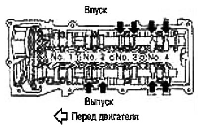
5. Guided by the figure, use a feeler gauge to measure the valve clearances in the places marked with the mark «X», as indicated in the table below (in fig. places are marked with black arrows).
Piston of cylinder No. 1 at TDC on the compression stroke
| Cylinder | №1 | №2 | №3 | №4 | |
| No. 1 cylinder piston at TDC on the compression stroke | Inlet | X | X | ||
| Release | X | X | |||
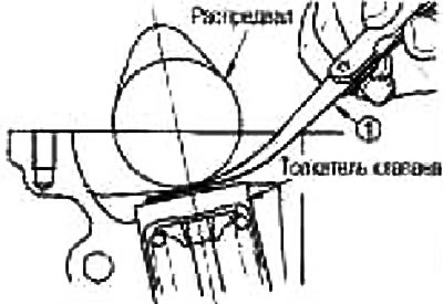
Standard valve clearances:
Unit - mm
| Hot engine | Cold engine* | |
| Inlet | 0,314-0,426 | 0,29-0,37 |
| Release | 0,338-0,462 | 0,32-0,40 |
*About 20°C (reference data)
If the test was carried out on a cold engine, make sure that the clearance values on a warm engine are still within the normal range.
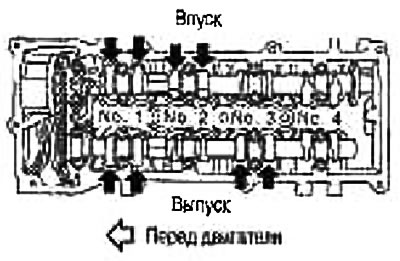
6. Rotate the crankshaft pulley 360°clockwise (when viewed from the front of the engine) and set the #4 cylinder piston to TDC on the compression stroke.
7. Guided by the figure, use a feeler gauge to measure the valve clearances in the places marked with the mark «X», as indicated in the table below (in the figure, the places are marked with black arrows).