


1. Remove the rocker arm cover.
2. Measure the valve clearance as follows:
a. Set the piston of the first cylinder to the top dead center position of the compression stroke:
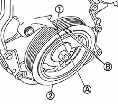
Turn the crankshaft pulley (2) clockwise until the TDC mark aligns (top dead center) (mark without paint) (A) with pointer (1) on the front cover. White marks (B) are not used for engine maintenance.
At the same time, make sure that the protrusions of the intake and exhaust cams of the first cylinder are directed outward, as shown in the figure.
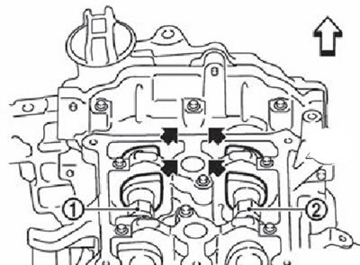
1. Camshaft (intake).
2. Camshaft (exhaust).
The arrow shows the front of the engine.
If the cams are not pointing outward as shown in the illustration, rotate the crankshaft pulley 360° once and set the cams as shown.
b. Using a set of flat feeler gauges (A), measure the clearance between the valve lifter and the camshaft.
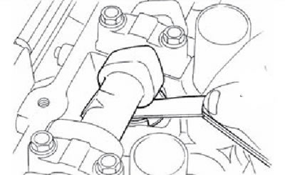
Using the figure below as a guide, measure the valve clearances at the locations indicated by the arrows in the figure or marked with an "x" in the table.
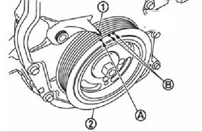

c. Turn the crankshaft pulley (2) one revolution (360°) until the TDC mark coincides (top dead center) (mark without paint) (A) with pointer (1) on the front cover. White marks (B) are not used for engine maintenance.
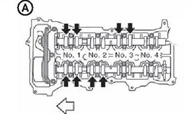
Using the figure below as a guide, measure the valve clearances at the locations indicated by black arrows in the figure or marked with an "x" in the table.
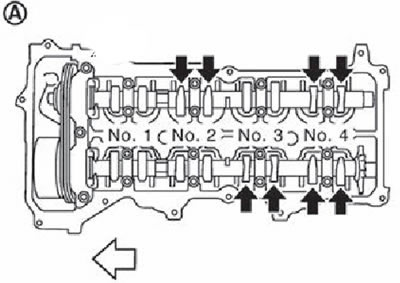
A: The piston of the fourth cylinder at the top dead center of the compression stroke. The arrow shows the front of the engine.
3. If the measurement values do not correspond to the norm, perform the adjustment procedure.

Nominal valve clearance:
- Inlet: 0.30mm
- Outlet: 0.33 mm.