


Car gearbox Nissan Qashqai 1 (J10)

Service Warnings and Precautions When Working on a Manual Transmission
If the transmission assembly is removed from the vehicle, the concentric clutch slave cylinder must always be replaced. To remove the transmission assembly, return the...
If the transmission assembly is removed from the vehicle, the concentric clutch slave cylinder must always be replaced. To remove the transmission assembly, return the...
Engine and Automatic Transmission On-Board Diagnostic (OBD) Precautions
Electronic engine control unit (ECM) equipped with an on-board diagnostic system. In the event of a deterioration in the efficiency of the exhaust emission control...
Electronic engine control unit (ECM) equipped with an on-board diagnostic system. In the event of a deterioration in the efficiency of the exhaust emission control...

Precautions when replacing the electronic transmission control unit and CVT
After replacing the variator assembly, it is necessary to enter the new data correctly (Module ID) in the transmission ECU, and delete the error codes from the memory,...
After replacing the variator assembly, it is necessary to enter the new data correctly (Module ID) in the transmission ECU, and delete the error codes from the memory,...

Precautions when working on an automatic transmission or CVT
Before connecting or disconnecting the A/T harness connector, turn off the ignition and disconnect the negative battery terminal. This is due to the fact that voltage...
Before connecting or disconnecting the A/T harness connector, turn off the ignition and disconnect the negative battery terminal. This is due to the fact that voltage...

Procedure for Removing and Installing the Automatic Transmission and CVT Connector
Removing Turn locking ring counterclockwise. Remove the automatic transmission or CVT wire connector upwards. Automatic transmission: A. Locking ring. B. AT wire...
Removing Turn locking ring counterclockwise. Remove the automatic transmission or CVT wire connector upwards. Automatic transmission: A. Locking ring. B. AT wire...

Five-speed manual transmission RS5F92R
Checking the transmission oil level 1. Check for signs of transmission oil leaks on or around the gearbox housing. 2. Remove fill plug (1) with gasket from the gearbox...
Checking the transmission oil level 1. Check for signs of transmission oil leaks on or around the gearbox housing. 2. Remove fill plug (1) with gasket from the gearbox...

Six-speed manual transmission RS6F94R
Checking the transmission oil level 1. Check for signs of transmission oil leaks on or around the gearbox housing. 2. Remove fill plug (1) with gasket from the gearbox...
Checking the transmission oil level 1. Check for signs of transmission oil leaks on or around the gearbox housing. 2. Remove fill plug (1) with gasket from the gearbox...

Manual transmission RS6F52A
Transmission oil Drain (2WD modifications) 1. Start the engine and let it run to warm up the transmission. 2. Stop the engine. Remove the drain plug and drain the gear...
Transmission oil Drain (2WD modifications) 1. Start the engine and let it run to warm up the transmission. 2. Stop the engine. Remove the drain plug and drain the gear...

Automatic transmission fluid RE6F01A
Checking and adjusting the level 1. Check for automatic transmission fluid leaks. 2. Place the vehicle on a level surface and apply the parking brake. 3. Start the...
Checking and adjusting the level 1. Check for automatic transmission fluid leaks. 2. Place the vehicle on a level surface and apply the parking brake. 3. Start the...

Checking the parking speed of an automatic transmission RE6F01A — checking
1. Check the engine oil level in the engine. Refuel if necessary. 2. Travel by car for ten minutes in order to warm up the automatic transmission fluid to a temperature...
1. Check the engine oil level in the engine. Refuel if necessary. 2. Travel by car for ten minutes in order to warm up the automatic transmission fluid to a temperature...

Checking the pressure in the automatic transmission lines RE6F01A
1. Check the engine oil level in the engine and top up if necessary. 2. Travel by car for ten minutes in order to warm up the working fluid of the ayahomahic gearbox to...
1. Check the engine oil level in the engine and top up if necessary. 2. Travel by car for ten minutes in order to warm up the working fluid of the ayahomahic gearbox to...

Continuously variable transmission RE0F10A: working fluid
Level check The level check must be carried out on a variator warmed up to a temperature of 50-80°C. The verification procedure is as follows: 1. Check for fluid leaks....
Level check The level check must be carried out on a variator warmed up to a temperature of 50-80°C. The verification procedure is as follows: 1. Check for fluid leaks....

RE0F10A Transmission Variator Parking Speed Check — Check
1. Check the engine oil level, top up if necessary. 2. Make a trip in the car for ten minutes to warm up the working fluid of the variator to a temperature of 50-80°C....
1. Check the engine oil level, top up if necessary. 2. Make a trip in the car for ten minutes to warm up the working fluid of the variator to a temperature of 50-80°C....

Checking the pressure in the lines of the variator of the gearbox RE0F10A — check
1. Check the engine oil level in the engine and top up if necessary. 2. Make a trip by car for ten minutes in order to warm up the working fluid of the variator to a...
1. Check the engine oil level in the engine and top up if necessary. 2. Make a trip by car for ten minutes in order to warm up the working fluid of the variator to a...

Five-speed manual transmission RS5F92R — device
1. 5th gear drive gear. 2. Fifth gear/reverse synchronizer assembly. 3. Primary shaft. 4. Secondary shaft. 5. Driven gear of the fifth gear. 6. Rear output shaft...
1. 5th gear drive gear. 2. Fifth gear/reverse synchronizer assembly. 3. Primary shaft. 4. Secondary shaft. 5. Driven gear of the fifth gear. 6. Rear output shaft...

Removing and installing gearbox RS5F92R assembly
1. Gearbox assembly. Note. : observe the installation direction and tightening torques of the bolts. Attention. If the gearbox assembly is removed. from the vehicle,...
1. Gearbox assembly. Note. : observe the installation direction and tightening torques of the bolts. Attention. If the gearbox assembly is removed. from the vehicle,...

RS5F92R Gearbox Control Rods — Device
1. Bracket. 2. Shift cable. 3. Control arm assembly. 4. Rope mounting bracket. 5. Threaded bolt. 6. Selection cable. 7. Seal. 8. Switching mechanism assembly. 9....
1. Bracket. 2. Shift cable. 3. Control arm assembly. 4. Rope mounting bracket. 5. Threaded bolt. 6. Selection cable. 7. Seal. 8. Switching mechanism assembly. 9....

Features of removal and installation of control rods of the RS5F92R gearbox
When removing: To disconnect the control cable from the control arm assembly, press the latches in the direction of the arrows in the figure. To remove the control cable...
When removing: To disconnect the control cable from the control arm assembly, press the latches in the direction of the arrows in the figure. To remove the control cable...

Six-speed manual transmission RS6F94R — device
1. Clutch housing. 2. Concentric clutch release cylinder. 3. Axis of the idle gear of the reverse gear. 4. Reverse drive gear. 5. Driven gear for reverse gear. 6. 2nd...
1. Clutch housing. 2. Concentric clutch release cylinder. 3. Axis of the idle gear of the reverse gear. 4. Reverse drive gear. 5. Driven gear for reverse gear. 6. 2nd...

Gearbox Assembly RS6F94R — Device
Attention. If the transmission assembly is removed from the vehicle, the concentric clutch release cylinder must be replaced. To remove the gearbox, return the insert of...
Attention. If the transmission assembly is removed from the vehicle, the concentric clutch release cylinder must be replaced. To remove the gearbox, return the insert of...

Removing and installing gearbox assembly RS6F94R
The procedures for removing and installing the RS6F94R gearbox are the same as those for the RS5F92R gearbox (see above in this chapter). Note. Tighten the bolts...
The procedures for removing and installing the RS6F94R gearbox are the same as those for the RS5F92R gearbox (see above in this chapter). Note. Tighten the bolts...
RS6F94R gearbox — check after installation
Attention. The gearbox assembly must not cling to the wiring harnesses and hydraulic clutch lines. When installing, the gearbox assembly must not be allowed to contact...
Attention. The gearbox assembly must not cling to the wiring harnesses and hydraulic clutch lines. When installing, the gearbox assembly must not be allowed to contact...

Gearbox Control Rods RS6F94R — Device
1. Bracket. 2. Shift cable. 3. Selection lever. 4. Switch lever. 5. Threaded bolt. 6. Rope mounting bracket. 7. Selection cable. 8. Seal. 9. Switching mechanism...
1. Bracket. 2. Shift cable. 3. Selection lever. 4. Switch lever. 5. Threaded bolt. 6. Rope mounting bracket. 7. Selection cable. 8. Seal. 9. Switching mechanism...

Control rod adjustment features for RS6F94R gearbox
Note. Control rod removal and installation procedures for the RS6F94R gearbox are the same as those for the RS5F92R gearbox (see earlier in this chapter). Slide the...
Note. Control rod removal and installation procedures for the RS6F94R gearbox are the same as those for the RS5F92R gearbox (see earlier in this chapter). Slide the...

Six-speed manual transmission RS6F52A — device
2WD Version: 1. Transmission housing. 2. Third gear drive gear. 3. Third/fourth gear synchronizer hub. 4. Third/fourth gear synchronizer clutch. 5. 4th gear drive. 6....
2WD Version: 1. Transmission housing. 2. Third gear drive gear. 3. Third/fourth gear synchronizer hub. 4. Third/fourth gear synchronizer clutch. 5. 4th gear drive. 6....

Gearbox Assembly RS6F52A — Device
Attention. If the transmission assembly is removed from the vehicle, the concentric clutch slave cylinder must always be replaced. To remove the transmission assembly,...
Attention. If the transmission assembly is removed from the vehicle, the concentric clutch slave cylinder must always be replaced. To remove the transmission assembly,...

Removing and installing gearbox RS6F52A assembly
The procedures for removing and installing the RS6F52A gearbox are the same as those for the RS5F92R gearbox (see above in this chapter). Note. Tighten the bolts...
The procedures for removing and installing the RS6F52A gearbox are the same as those for the RS5F92R gearbox (see above in this chapter). Note. Tighten the bolts...
RS6F52A gearbox — check after installation
Attention. The gearbox assembly must not cling to the wiring harnesses and hydraulic clutch lines. When installing the transmission assembly, do not allow the input...
Attention. The gearbox assembly must not cling to the wiring harnesses and hydraulic clutch lines. When installing the transmission assembly, do not allow the input...

Gearbox Control Rods RS6F52A — Device
1. Bracket. 2. Shift cable. 3. Shift lever A. 4. Selection lever. 5. Rope mounting bracket. 6. Selection cable. 7. Seal. 8. Gearshift mechanism assembly. 9. Backstage....
1. Bracket. 2. Shift cable. 3. Shift lever A. 4. Selection lever. 5. Rope mounting bracket. 6. Selection cable. 7. Seal. 8. Gearshift mechanism assembly. 9. Backstage....

Control rod adjustment features for RS6F52A gearbox
Note. Control rod removal and installation procedures for RS6F52A gearbox are the same as those for RS5F92R gearbox (see above in this chapter). Slide the latch (1)...
Note. Control rod removal and installation procedures for RS6F52A gearbox are the same as those for RS5F92R gearbox (see above in this chapter). Slide the latch (1)...
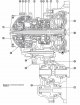
Six-speed automatic transmission RE6F01A — device
1. Torque converter housing. 2. Oil pump. 3. Coupling «3-5 reverse». 4. Front planetary gear. 5. Low clutch. 6. Output gear. 7. Brake for low gear and reverse gear. 8....
1. Torque converter housing. 2. Oil pump. 3. Coupling «3-5 reverse». 4. Front planetary gear. 5. Low clutch. 6. Output gear. 7. Brake for low gear and reverse gear. 8....

Gearbox RE6F01A assembly — device
1. Turbine speed sensor. 2. O-ring. 3. O-ring. 4. Hairpin. 5. Automatic transmission fluid level tube. 6. Drain plug. 7. O-ring. 8. Automatic transmission assembly. 9....
1. Turbine speed sensor. 2. O-ring. 3. O-ring. 4. Hairpin. 5. Automatic transmission fluid level tube. 6. Drain plug. 7. O-ring. 8. Automatic transmission assembly. 9....

Gearbox RE6F01A assembly — removal and installation
Attention. Do not remove the coolant expansion tank cap when the engine is hot. Hot coolant can spray out under pressure and cause severe burns. Removing 1. Using a...
Attention. Do not remove the coolant expansion tank cap when the engine is hot. Hot coolant can spray out under pressure and cause severe burns. Removing 1. Using a...

Gearbox RE6F01A assembly — checks
Check before installation After inserting the torque converter into the automatic transmission, make sure that the distance (A) complies with the established norm. A....
Check before installation After inserting the torque converter into the automatic transmission, make sure that the distance (A) complies with the established norm. A....

RE6F01A automatic transmission control — device
1. The sides of the knob. 2. Selector lever knob. 3. Locking pin. 4. Position indicator. 5. Shift lock solenoid. 6. Switching mechanism assembly. 7. Indicator plate. 8....
1. The sides of the knob. 2. Selector lever knob. 3. Locking pin. 4. Position indicator. 5. Shift lock solenoid. 6. Switching mechanism assembly. 7. Indicator plate. 8....

Features of removing and installing the control rod of an automatic transmission RE6F01A
When installing the control cable (1) to shift mechanism assembly (2) make sure that the control cable is installed with a ribbed surface (A) up and pressed all the way....
When installing the control cable (1) to shift mechanism assembly (2) make sure that the control cable is installed with a ribbed surface (A) up and pressed all the way....

Checking and adjusting the position of automatic transmission modes RE6F01А
Examination 1. Place the selector lever in position "R" and turn the ignition switch to position "ON" (do not start the engine). 2. Make sure that the selector lever can...
Examination 1. Place the selector lever in position "R" and turn the ignition switch to position "ON" (do not start the engine). 2. Make sure that the selector lever can...

RE0F10A continuously variable automatic transmission — device
1. Torque converter housing. 2. Driven sprocket. 3. Chain. 4. Reverse brake. 5. Oil pump. 6. Forward clutch. 7. Planetary gear. 8. Primary pulley. 9. Sun gear. 10. Steel...
1. Torque converter housing. 2. Driven sprocket. 3. Chain. 4. Reverse brake. 5. Oil pump. 6. Forward clutch. 7. Planetary gear. 8. Primary pulley. 9. Sun gear. 10. Steel...

RE0F10A gearbox variator assembly — device
1. CVT fluid level dipstick. 2. CVT filling pipe. 3. O-ring. 4. Gearbox assembly. 5. Breather hose. Note. : replace the part with a new one after each removal. : Apply...
1. CVT fluid level dipstick. 2. CVT filling pipe. 3. O-ring. 4. Gearbox assembly. 5. Breather hose. Note. : replace the part with a new one after each removal. : Apply...

Removal and installation of RE0F10A gearbox variator assembly
Attention. Do not remove the coolant expansion tank cap when the engine is hot. Hot coolant can spray out under pressure and cause severe burns. Removing 1. Remove the...
Attention. Do not remove the coolant expansion tank cap when the engine is hot. Hot coolant can spray out under pressure and cause severe burns. Removing 1. Remove the...

RE0F10A gearbox variator assembly — check
Check before installation After inserting the torque converter into the variator, make sure that the distance (A) complies with the established norm. A. Measured...
Check before installation After inserting the torque converter into the variator, make sure that the distance (A) complies with the established norm. A. Measured...

Stepless transmission control RE0F10A — device
1. Control cable. 2. Locking plate. 3. Bracket. 4. Gearbox assembly. 5. Bracket. 6. Switching mechanism assembly. A. Shift lever.
1. Control cable. 2. Locking plate. 3. Bracket. 4. Gearbox assembly. 5. Bracket. 6. Switching mechanism assembly. A. Shift lever.
Features of removing and installing the control rod of the continuously variable gearbox RE0F10A
See similar section for automatic transmission RE6F01A ( see earlier in this chapter ).
See similar section for automatic transmission RE6F01A ( see earlier in this chapter ).

Checking and adjusting the position of automatic transmission modes RE0F10A
Examination 1. Place the silicone lever in position "R" and turn the ignition switch to the position "ON" (do not start the engine). 2. Make sure that the silicone lever...
Examination 1. Place the silicone lever in position "R" and turn the ignition switch to the position "ON" (do not start the engine). 2. Make sure that the silicone lever...


Six-speed manual transmission RS6F52A — service data and specification
Axial play Gap in the blocking ring of the synchronizer Modification with MR20DE engine M9R Dimensions The moment of resistance to rotation of the side bearing of the...
Axial play Gap in the blocking ring of the synchronizer Modification with MR20DE engine M9R Dimensions The moment of resistance to rotation of the side bearing of the...

Six-speed automatic transmission RE6F01A — service data and specification
Attention. Use genuine NISSAN Matic J ATF automatic transmission fluid. The use of other fluid levels will adversely affect the performance of the automatic transmission...
Attention. Use genuine NISSAN Matic J ATF automatic transmission fluid. The use of other fluid levels will adversely affect the performance of the automatic transmission...

CVT RE0F10A — service data and specification
Attention. Use only genuine NISSAN CVT fluid NS-2. Do not mix with other liquids. The use of any other fluids will adversely affect the performance of the variator and...
Attention. Use only genuine NISSAN CVT fluid NS-2. Do not mix with other liquids. The use of any other fluids will adversely affect the performance of the variator and...

This section is available on: russian, bulgarian, belarusian, ukrainian, serbian, croatian, romanian, polish, slovak, hungarian
Similar information for other Nissan models
➜ Transmission: Manual gearbox Nissan Almera 1 (1995-2000)
➜ Transmission: Mechanical gearbox Nissan Maxima 4 (1994-1999)
➜ Transmission: Mechanical gearbox Nissan Terrano 1 (1986-1995, petrol)
➜ Transmission: Mechanical gearbox Nissan Patrol 4 (1987-1997, petrol)
➜ Transmission: Mechanical gearbox Nissan Example 1 (1990-1996, petrol)
➜ Transmission: Mechanical gearbox Nissan Sunny 7 (1990-1998)
➜ Transmission: Mechanical gearbox Nissan Micra 3 (2002-2010, petrol)
Link in different formats to this section
TEXTHTMLBB Code
- General information
- Faults en route
- Daily checks
- User manual
- Maintenance
- Power unit
- Petrol engines 1.6L (HR16)
- Petrol engines 2.0L (MR20)
- Diesel engines 1.5L (K9K)
- Diesel engines 2.0L (M9R)
- Cooling system
- Engine lubrication system
- Engine power system
- Engine management system
- Intake and exhaust system
- Engine electrical equipment
- Transmission
- Clutch
- Car gearbox
- Transfer case and shafts
- Chassis
- Car suspension
- Brake system
- Steering
- Body
- Exterior (external elements)
- Interior (internal elements)
- Safety system
- Heating and air conditioning
- Electrical equipment
- Wiring harnesses
NissanBook.ru © 2018–2024 · Mobile version · Articles about Nissan · Sitemap: EN BG BY UA RS HR RO PL SK HU · Feedback · Site search · Bookmark
Almera 1 (N15) · Maxima 4 (A32) · Terrano 1 (petrol) · Patrol 4 (Y60, petrol) · Example 1 (P10, petrol) · Qashqai 1 (J10) · Serena 2 (C24) · Sunny 7 (B13) · Note 1 · Micra 3 (petrol) ·
Almera 1 (N15) · Maxima 4 (A32) · Terrano 1 (petrol) · Patrol 4 (Y60, petrol) · Example 1 (P10, petrol) · Qashqai 1 (J10) · Serena 2 (C24) · Sunny 7 (B13) · Note 1 · Micra 3 (petrol) ·