Note. Control rod removal and installation procedures for the RS6F94R gearbox are the same as those for the RS5F92R gearbox (see earlier in this chapter).
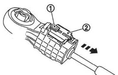
Slide the latch (1) selector cable in the direction of the arrow in the illustrations to remove the stopper (2).
Install the end of the selector cable onto the pin of the shifter assembly.
Install lock pin (1) or a 3mm diameter rod into the shifter assembly.
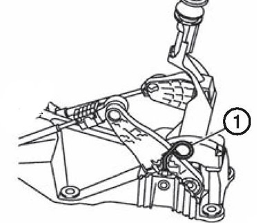
Note. The selection cable cannot be adjusted accurately without the use of a locking pin or a 3 mm rod.
Make sure that the gate does not move in the direction of selection. If not, repeat the above procedure.
Move the link to the fourth gear position.
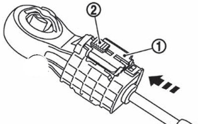
Having pressed the stopper (1) selector cable as far as it will go, slide the latch (2) as far as it will go in the direction of the arrow in the figures.
Remove the locking pin or 3 mm diameter rod from the shift mechanism.
Moving the link in each of the switching positions, check for jamming. If the link does not move smoothly, repeat the adjustment procedure from the beginning.
After installation, check the following:
By moving the link in the direction of the first-second gears and in the direction of the fifth-sixth gears, make sure that the link returns to the neutral position on its own.
When moving the yoke in each of the positions, make sure that the boot does not bulge or detach.