


Gasoline engine HR16 of cars Nissan Qashqai 1 (J10)

Precautions when working with the hood top panel removed
When carrying out work with the upper part of the hood panel removed, it is necessary to cover the lower edge of the windshield with a polyurethane strip or other...
When carrying out work with the upper part of the hood panel removed, it is necessary to cover the lower edge of the windshield with a polyurethane strip or other...

Valve clearances — check
After removing, installing or replacing the camshaft or elements of the gas distribution mechanism, as well as if there are suspicions about a malfunction of the gas...
After removing, installing or replacing the camshaft or elements of the gas distribution mechanism, as well as if there are suspicions about a malfunction of the gas...

Compression in the cylinders — check
1. Fully warm up and then stop the engine. 2. Depressurize the fuel lines. 3. Remove coils and spark plugs from each cylinder. 4. Connect the tachometer to the engine...
1. Fully warm up and then stop the engine. 2. Depressurize the fuel lines. 3. Remove coils and spark plugs from each cylinder. 4. Connect the tachometer to the engine...

Engine Assembly — Device
1. Right engine mounting pad. 2. Right engine mounting bracket. 3. Engine mount. 4. Rear engine mounting bracket. 5. Rear torsion bar. 6. Left engine mounting bracket....
1. Right engine mounting pad. 2. Right engine mounting bracket. 3. Engine mount. 4. Rear engine mounting bracket. 5. Rear torsion bar. 6. Left engine mounting bracket....

Removing the engine assembly
Attention. Park the vehicle on a flat, firm surface. Place wheel chocks in front of and behind the rear wheels. Install the lifting eyes described in the spare parts...
Attention. Park the vehicle on a flat, firm surface. Place wheel chocks in front of and behind the rear wheels. Install the lifting eyes described in the spare parts...

Installing the engine assembly
Installation is carried out in the reverse order of removal, taking into account the following: Do not allow engine oil to get on the elastic elements of the engine...
Installation is carried out in the reverse order of removal, taking into account the following: Do not allow engine oil to get on the elastic elements of the engine...

Installing the engine on a stand for disassembly
Note. The following is a description of mounting the engine on a disassembly stand using the bearing surface on the gearbox side. When using a bench of a different...
Note. The following is a description of mounting the engine on a disassembly stand using the bearing surface on the gearbox side. When using a bench of a different...

Engine disassembly and assembly
Disassembly 1. Remove intake manifold (see chapter " Intake and exhaust system "). 2. Remove exhaust manifold (see chapter " Intake and exhaust system "). 3. Remove the...
Disassembly 1. Remove intake manifold (see chapter " Intake and exhaust system "). 2. Remove exhaust manifold (see chapter " Intake and exhaust system "). 3. Remove the...

Attachment Drive Belt — Check
Attention. Checking the belts is carried out exclusively on a cold engine or after half an hour after it has stopped. 1. Visually check the belt for wear, damage and...
Attention. Checking the belts is carried out exclusively on a cold engine or after half an hour after it has stopped. 1. Visually check the belt for wear, damage and...

Belt tension adjustment
Attention. Before checking the deflection of a newly installed belt, it is necessary to adjust its tension. Rotate the crankshaft at least two revolutions, adjust the...
Attention. Before checking the deflection of a newly installed belt, it is necessary to adjust its tension. Rotate the crankshaft at least two revolutions, adjust the...

Removing the drive belt
1. Loosen the lock nut (A) intermediate pulley and by turning the adjusting bolt (IN), loosen the tension of the drive belt. 1. Generator. 2. Water pump. 3. Crankshaft...
1. Loosen the lock nut (A) intermediate pulley and by turning the adjusting bolt (IN), loosen the tension of the drive belt. 1. Generator. 2. Water pump. 3. Crankshaft...
Installing the drive belt
1. Belts are installed in the reverse order of removal. Attention. The belt must properly lie down in the pulley streams. Keep engine oil and coolant away from the belt...
1. Belts are installed in the reverse order of removal. Attention. The belt must properly lie down in the pulley streams. Keep engine oil and coolant away from the belt...

The drive chain of the gas distribution mechanism is a device
1. Drive chain tensioner shoe. 2. Timing chain tensioner. 3. An asterisk of a final camshaft. 4. Intake camshaft sprocket. 5. Plug. 6. Front oil seal. 7. Crankshaft...
1. Drive chain tensioner shoe. 2. Timing chain tensioner. 3. An asterisk of a final camshaft. 4. Intake camshaft sprocket. 5. Plug. 6. Front oil seal. 7. Crankshaft...

Gas distribution mechanism — removal
Attention. The direction of rotation referred to below is seen from the front of the engine. 1. Remove the front right wheel. 2. Remove the right fender liner. 3. Drain...
Attention. The direction of rotation referred to below is seen from the front of the engine. 1. Remove the front right wheel. 2. Remove the right fender liner. 3. Drain...
Gas distribution mechanism — device
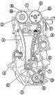
Note. The figure shows the alignment of the timing marks on the drive chain and the corresponding sprockets after the components have been installed. 1. Timing chain...
Note. The figure shows the alignment of the timing marks on the drive chain and the corresponding sprockets after the components have been installed. 1. Timing chain...

Gas distribution mechanism — checks
Checking the drive chain after removal Check for cracks and excessive wear on the drive chain link plates and rollers. If necessary, replace the drive chain with a new...
Checking the drive chain after removal Check for cracks and excessive wear on the drive chain link plates and rollers. If necessary, replace the drive chain with a new...

Camshafts — device
1. Camshaft covers (№2-5). 2. Camshaft cover (№1). 3. An asterisk of a final camshaft. 4. Intake camshaft sprocket. 5. Gyalovka cylinder block. 6. Oil filter (intake...
1. Camshaft covers (№2-5). 2. Camshaft cover (№1). 3. An asterisk of a final camshaft. 4. Intake camshaft sprocket. 5. Gyalovka cylinder block. 6. Oil filter (intake...

Camshafts — removal
Note. This section contains procedures for removing and installing the camshaft with the engine front cover installed. If the engine front cover was previously removed,...
Note. This section contains procedures for removing and installing the camshaft with the engine front cover installed. If the engine front cover was previously removed,...

Camshafts — installation
1. Install oil filters (1) (inlet side and outlet side), by assembling it with a cork (3) and inserting it into the cylinder head. 1. Oil filter. 2. Washer. 3. Plug. 2....
1. Install oil filters (1) (inlet side and outlet side), by assembling it with a cork (3) and inserting it into the cylinder head. 1. Oil filter. 2. Washer. 3. Plug. 2....

Camshafts — checks after removal
Oil filter Make sure there is no oil in the oil filter (1) foreign material and check for blockages. Check filter for damage. If any defects are found, replace the oil...
Oil filter Make sure there is no oil in the oil filter (1) foreign material and check for blockages. Check filter for damage. If any defects are found, replace the oil...

Camshafts — checks after installation
Note. Below are the procedures for checking for fluid and lubricant leaks. 1. Before starting the engine, check the levels of oil and engine fluids. If not enough, top...
Note. Below are the procedures for checking for fluid and lubricant leaks. 1. Before starting the engine, check the levels of oil and engine fluids. If not enough, top...

Cylinder head cover (rocker cover) — device
1. Ignition coil. 2. Spark plug. 3. Hose of the forced crankcase ventilation system. 4. Oil fill cap. 5. Rocker cover. 6. Gasket. 7. Bracket. 8. Sleeve. 9. Valve of the...
1. Ignition coil. 2. Spark plug. 3. Hose of the forced crankcase ventilation system. 4. Oil fill cap. 5. Rocker cover. 6. Gasket. 7. Bracket. 8. Sleeve. 9. Valve of the...

Cylinder head cover — removal and installation
Removing 1. Remove intake manifold (see chapter " Intake and exhaust system "). 2. Remove ignition coils. Attention. Do not hit or drop ignition coils. Do not...
Removing 1. Remove intake manifold (see chapter " Intake and exhaust system "). 2. Remove ignition coils. Attention. Do not hit or drop ignition coils. Do not...

Cylinder head assembly — device
1. Cylinder head assembly. 2. Cylinder head bolt. 3. Washer. 4. Laying of a head of the block of cylinders. Note. A: See the tightening procedure in the text of the...
1. Cylinder head assembly. 2. Cylinder head bolt. 3. Washer. 4. Laying of a head of the block of cylinders. Note. A: See the tightening procedure in the text of the...

Removing the cylinder head
1. Relieve fuel pressure in fuel lines (see chapter " Supply system "). 2. Drain coolant and engine oil. Attention. Perform these procedures only on a cold engine. Do...
1. Relieve fuel pressure in fuel lines (see chapter " Supply system "). 2. Drain coolant and engine oil. Attention. Perform these procedures only on a cold engine. Do...

Installing the cylinder head
1. Install a new cylinder head gasket. 2. Tighten the cylinder head bolts in sequence as follows: A. Release side. B. Inlet side. Attention. If the cylinder head bots...
1. Install a new cylinder head gasket. 2. Tighten the cylinder head bolts in sequence as follows: A. Release side. B. Inlet side. Attention. If the cylinder head bots...

Cylinder head — device
1. Spark plug. 2. Valve crackers. 3. Valve plate. 4. Valve spring. 5. Valve spring seat. 6. Oil cap. 7. Exhaust valve guide. 8. Intake valve guide. 9. Cylinder head. 10....
1. Spark plug. 2. Valve crackers. 3. Valve plate. 4. Valve spring. 5. Valve spring seat. 6. Oil cap. 7. Exhaust valve guide. 8. Intake valve guide. 9. Cylinder head. 10....

Dismantling of a head of the block of cylinders
1. Remove the spark plugs with a special key. 2. Remove the valve lifters, having previously noted the position of their installation, and arrange them in order without...
1. Remove the spark plugs with a special key. 2. Remove the valve lifters, having previously noted the position of their installation, and arrange them in order without...

Cylinder head assembly
1. Install the valve guides if removed: Note. Install valve guide bushings oversized by 0.2 mm over the nominal size. Using a valve guide reamer (A) (special tool) bore...
1. Install the valve guides if removed: Note. Install valve guide bushings oversized by 0.2 mm over the nominal size. Using a valve guide reamer (A) (special tool) bore...

Cylinder head — checks after removal
1. Outer diameter of cylinder head bolts: Cylinder head bolts thin out during use. Whenever the difference between the diameters «d1» And «d2» exceeds the limit value...
1. Outer diameter of cylinder head bolts: Cylinder head bolts thin out during use. Whenever the difference between the diameters «d1» And «d2» exceeds the limit value...

Cylinder head — check after disassembly
Valve sizes Check the dimensions of each valve. If the measurements obtained are not correct, replace the valve with a new one and check the contact of the valve with...
Valve sizes Check the dimensions of each valve. If the measurements obtained are not correct, replace the valve with a new one and check the contact of the valve with...
Cylinder block and connecting rod and piston group — device
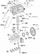
1. Crankshaft position sensor cover. 2. Crankshaft position sensor (POS). 3. O-ring of circular cross-section. 4. Coolant drain plug. 5. Cylinder block. 6. Oil dipstick....
1. Crankshaft position sensor cover. 2. Crankshaft position sensor (POS). 3. O-ring of circular cross-section. 4. Coolant drain plug. 5. Cylinder block. 6. Oil dipstick....

Cylinder block and connecting rod and piston group — disassembly
1. Remove the upper part of the oil pan. 2. Remove the cylinder head. 3. Remove the knock sensor. Attention. Do not strike the knock sensor. 4. Remove the crankshaft...
1. Remove the upper part of the oil pan. 2. Remove the cylinder head. 3. Remove the knock sensor. Attention. Do not strike the knock sensor. 4. Remove the crankshaft...

Cylinder block and connecting rod and piston group — assembly
1. Completely blow out the cooling system jacket and cylinder oil, as well as the cylinder bores, with compressed air to remove foreign materials. Attention. Use goggles...
1. Completely blow out the cooling system jacket and cylinder oil, as well as the cylinder bores, with compressed air to remove foreign materials. Attention. Use goggles...

Cylinder block and connecting rod and piston group — check
Note. Nominal and maximum permissible values are given in section «Service data and specification» of this chapter. 1. Axial clearance of the crankshaft: Dial indicator...
Note. Nominal and maximum permissible values are given in section «Service data and specification» of this chapter. 1. Axial clearance of the crankshaft: Dial indicator...

Selection of pistons and bearing shells — description
The size group number is stamped on each part and corresponds to the specific size range of the new part. For used ones, this designation of the size group is not valid....
The size group number is stamped on each part and corresponds to the specific size range of the new part. For used ones, this designation of the size group is not valid....

Selection of connecting rod bearings
A) For a new connecting rod and a used crankshaft: 1. Determine the size group of the diameter of the stamp (WITH) on the side of the connecting rod for row table...
A) For a new connecting rod and a used crankshaft: 1. Determine the size group of the diameter of the stamp (WITH) on the side of the connecting rod for row table...

The use of connecting rod bearings of repair size groups
In the case when, when using liners of standard size groups, the specified value of the oil clearance is not ensured, liners of repair size groups should be used (US)....
In the case when, when using liners of standard size groups, the specified value of the oil clearance is not ensured, liners of repair size groups should be used (US)....

Selection of root bearings
A) For a new cylinder block and used crankshaft: 1. Horizontal rows in a table "Selection of the thickness of the main bearings" correspond to the size group of the main...
A) For a new cylinder block and used crankshaft: 1. Horizontal rows in a table "Selection of the thickness of the main bearings" correspond to the size group of the main...

Application of main bearings of repair size groups
In the case when, when using liners of standard size groups, the specified value of the oil clearance is not ensured, liners of repair size groups should be used (US)....
In the case when, when using liners of standard size groups, the specified value of the oil clearance is not ensured, liners of repair size groups should be used (US)....


Service Data
Valve timing Valve timing diagram (with the intake valve phase shifter on) Note. In parentheses are the values when the phase shifter is turned on. The white arrow...
Valve timing Valve timing diagram (with the intake valve phase shifter on) Note. In parentheses are the values when the phase shifter is turned on. The white arrow...

This section is available on: russian, bulgarian, belarusian, ukrainian, serbian, croatian, romanian, polish, slovak, hungarian
Similar information for other Nissan models
➜ Power unit: Control system (gasoline) Nissan Almera 1 (1995-2000)
➜ Power unit: Petrol engine SR20DE Nissan Serena 2 (1999-2005)
Link in different formats to this section
TEXTHTMLBB Code
- General information
- Faults en route
- Daily checks
- User manual
- Maintenance
- Power unit
- Petrol engines 1.6L (HR16)
- Petrol engines 2.0L (MR20)
- Diesel engines 1.5L (K9K)
- Diesel engines 2.0L (M9R)
- Cooling system
- Engine lubrication system
- Engine power system
- Engine management system
- Intake and exhaust system
- Engine electrical equipment
- Transmission
- Clutch
- Car gearbox
- Transfer case and shafts
- Chassis
- Car suspension
- Brake system
- Steering
- Body
- Exterior (external elements)
- Interior (internal elements)
- Safety system
- Heating and air conditioning
- Electrical equipment
- Wiring harnesses
NissanBook.ru © 2018–2024 · Mobile version · Articles about Nissan · Sitemap: EN BG BY UA RS HR RO PL SK HU · Feedback · Site search · Bookmark
Almera 1 (N15) · Maxima 4 (A32) · Terrano 1 (petrol) · Patrol 4 (Y60, petrol) · Example 1 (P10, petrol) · Qashqai 1 (J10) · Serena 2 (C24) · Sunny 7 (B13) · Note 1 · Micra 3 (petrol) ·
Almera 1 (N15) · Maxima 4 (A32) · Terrano 1 (petrol) · Patrol 4 (Y60, petrol) · Example 1 (P10, petrol) · Qashqai 1 (J10) · Serena 2 (C24) · Sunny 7 (B13) · Note 1 · Micra 3 (petrol) ·