Attention. Use goggles to cover your eyes.
2. Install plug (1) into the coolant drain hole as shown in the figure. Use only branded silicone sealant or equivalent.
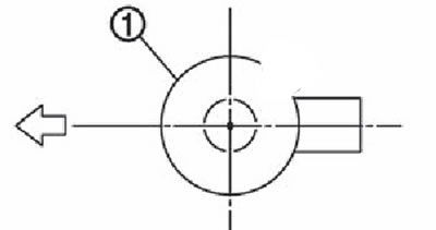
Note. The arrow points to the front of the engine.
3. Install the main bearing bushings and thrust rings as follows:
Remove dust, dirt and engine oil from the seats in the cylinder block.
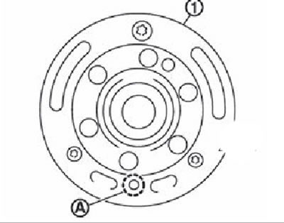
Install thrust washers on both sides of main bearing No. 3 (IN) cylinder block so that the sides with oil grooves (A) were directed towards the crankshaft (outside).
Note. The arrow points to the front of the engine.
Install main bearing bushings (1), paying attention to the fact that bearings with oil grooves (A) are installed in the cylinder block, and liners without grooves are installed in the covers of the main bearings. Before installing the liners, apply fresh engine oil to the inner (working) bearing surface. Do not apply oil to the outer surface of the liners - it must be clean.
Make sure the oil holes in the cylinder block line up with the holes in the bearings.
Install the bearing bushings as shown in the illustration.
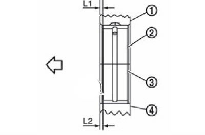
1. Cylinder block.
2. Top liner.
3. Bottom liner.
4. Main bearing cover.
Note. The arrow points to the front of the engine.
Note. Install the main bearing bushing in the center position, observing the following dimensions. During service, the center position can be determined visually.
Attention. Dimension L1 of support #3 is the distance from the edge of the housing (block) (not from the installation surface of the thrust ring).
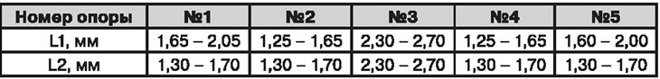
4. Install the signal disc on the crankshaft, if it was removed:
Install signal disc (1) surface with protrusions towards the balancer (engine front) on the back of the crankshaft.
Align dowel pin with hole (A) disc and tighten the bolt.
Note. The crankshaft locating pin and signal disc are a precision pair.
Remove dowel pin.
Attention. Make sure the dowel pin is removed.
5. Install the crankshaft in the cylinder block. Make sure the crankshaft rotates smoothly by hand.
Attention. At this stage, do not install the crankshaft rear oil seal.
6. Install the crankshaft main bearing caps, paying attention to the marks on the front (IN) and stamp number support (A).
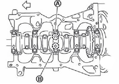
Note. The main bearing caps cannot be replaced individually as they are machined together with the cylinder block.
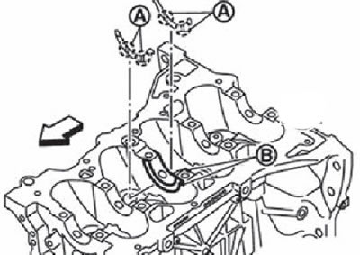
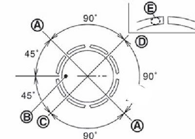
7. Tighten the main bearing cap bolts in the order shown in the figure as follows:
- Apply fresh engine oil to the threads and seating surfaces of the bolts.
- Tighten the main bearing cap bolts to 32.4 Nm.
Note. The arrow points to the front of the engine.
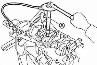
Tighten the main bearing cap bolts 60°clockwise (corner wrench) in the order shown in the figure.
Attention. Check and confirm the angle of the dotgahki with the angle knob (KV10112100) (A) or a transporter. Supplementation not recommended «approximately».
After installing the mounting bolts, make sure that the crankshaft turns freely by hand.
Check crankshaft end play.
8. Install the piston on the connecting rod as follows:
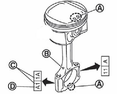
Install the piston and connecting rod so that the front mark (A) on the piston crown and cylinder number (WITH) on one side as shown in the picture.
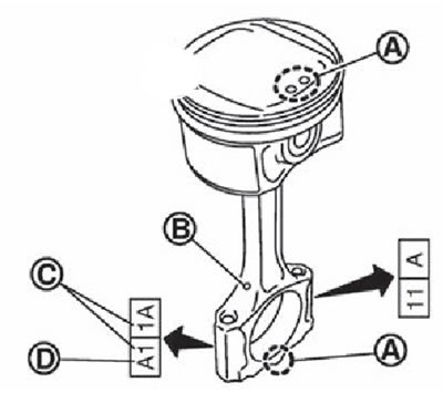
A. Front marks.
B. Oil groove.
C. Cylinder number.
D. Marking of the bottom head of the connecting rod.
Note. Symbols without a description are not used in the maintenance process.
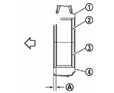
Press in the piston pin using a press.
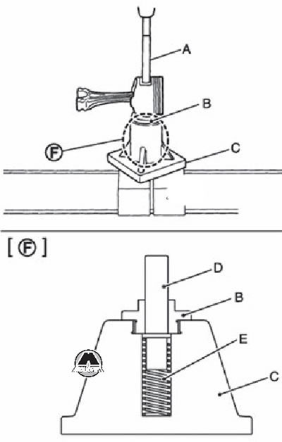
A. Mandrel (KV10109730).
B. Center cup (KV10110310).
C. Press base (ST13030020).
D. Central stem (KV10114120).
E. Spring (ST13030030).
F. Assembly of parts.
Attention. Be careful not to damage the piston pin during the pressing process.
Note. The piston pin is pressed into the upper head of the connecting rod.
Press in piston pin (2) to a depth of 2.35 mm from the piston surface (A).
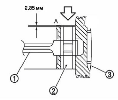
1. Connecting rod.
2. Piston pin.
3. Piston.
A. Piston surface.
Upon completion of work, make sure that the piston (3) rotates freely.
9. Using a ring expander, install the piston rings:
Attention.
- When installing the rings, be careful not to damage the piston.
- Do not push the rings too wide, so as not to break them.
Install the piston rings so that their locks are in position, while focusing on the front marks (IN) piston.
Install the second compression ring so that the stamp «R» on it was directed upwards.
A. Upper or lower oil scraper disc lock (any of them).
B. Front piston marks.
C. The lock of the second compression ring and the expander of the oil ring.
D. Upper compression ring lock.
10. Install the connecting rod bearings in the connecting rods and connecting rod caps:
When installing connecting rod bearings, apply fresh engine oil to the inner (working) insert surface. Do not apply oil to the outer surface of the liners - it must be clean.
Set the earbuds to the center position.
Note. The inserts do not have a locking lug.
Make sure the oil holes in the bushing and connecting rod match up.
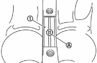
Install the connecting rod according to the dimensions shown in the figure.
1. Connecting rod.
2. Upper connecting rod bearing.
3. Lower connecting rod bearing.
4. Connecting rod cap.
A. 1.7-2.1 mm.
Note. The arrow points to the front of the engine.
Note. Install the stud bushing in the center position in accordance with the size «A». During service, the center position can be determined visually.
11. Install the piston with connecting rod assembly on the crankshaft:
- Place the crankshaft journal in the position corresponding to the bottom dead center of the piston.
- Apply fresh engine oil to the cylinder bore, piston and crankshaft journal.
- Position the pistons with connecting rods opposite the corresponding cylinder bores, referring to the numbers on the connecting rods.
- By crimping piston rings (EM03470000) (A), insert the piston into the cylinder so that the mark on the front of the piston faces the front of the engine.
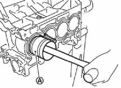
Attention.
- Be careful not to damage the contact surfaces of the connecting rod cap.
- Be careful not to damage the cylinder bore and crankshaft journal with the beating lower end of the connecting rod.
12. To establish a cover of the lower head of a rod. Align the cylinder number on the connecting rod (WITH) with the cylinder number on the connecting rod cap.
A. Front mark.
B. Oil groove.
C. Cylinder number.
D. Marking of the lower head of the shuttle.
13. Check the diameter of the connecting rod bolts.
14. Tighten the connecting rod bolts as follows:
- Apply fresh engine oil to the threads and seating surfaces of the connecting rod bolts.
- Tighten connecting rod bolts in several steps to 27.5 Nm.
- Completely loosen the connecting rod bolts.
- Tighten connecting rod bolts in several steps to 19.6 Nm.
- Tighten all bolts 60 degrees clockwise (corner wrench).
Attention. Check and confirm the tightening angle using the angle driver (KV10112100) (A) or conveyor. Tightening not recommended «approximately».
After tightening the connecting rod bolts, check that the crankshaft rotates freely.
Check the side clearance of the connecting rods.
15. Install the upper part of the oil pan.
Note. Press in the crankshaft rear oil seal after installing the upper part of the oil pan.
16. Press in the rear oil seal.
17. Install the flywheel and tighten the mounting bolts in a cross pattern in several steps.
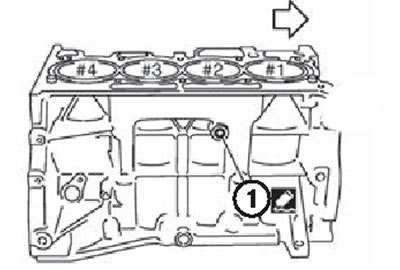
18. Install knock sensor (1) so that its connector is directed towards the rear of the engine.
Note. The arrow points to the front of the engine.
Attention.
- Do not tighten the mounting bolts while holding the sensor by the connector.
- If the sensor has been dropped or impacted, replace it with a new one.
Note.
- Check that there are no foreign materials on the contact surface of the cylinder block and the rear surface of the knock sensor.
- Make sure the knock sensor does not touch other parts of the engine.
19. Install the crankshaft position sensor (POS) cover and tighten the mounting bolts.
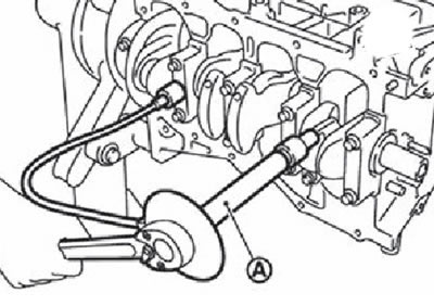
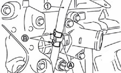
20. Insert the oil dipstick correction tube (1) into the cylinder block and fix it with holders (IN) near the holder (A) inlet pipe of the cooling system, as shown in the figure.
21. Further assembly is carried out in the reverse order of disassembly.