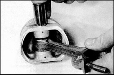
Correct mutual orientation of piston and connecting rod
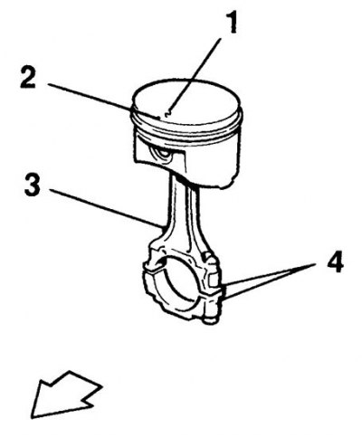
1. Piston size group number; 2. Orientation mark (in the form of an arrow); 3. Oil hole in the body of the connecting rod; 4. Place of drawing the number of the cylinder to which the connecting rod belongs (maybe on the other side)
1. Before checking, the connecting rods and pistons should be cleaned and the old rings removed from the piston.
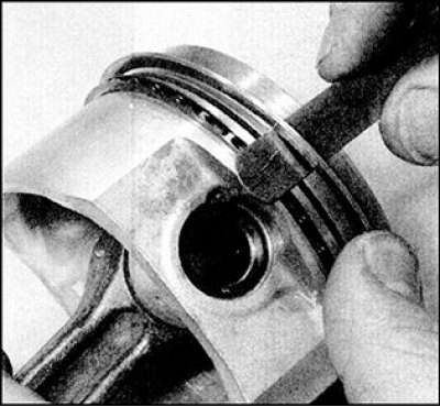
2. Carefully spread the ring out onto the top of the piston. To prevent the ring from falling into an empty groove when removing, place two or three old probes under the ring.
3. When removing the rings, do not damage the piston surfaces with sharp edges. Rings are very brittle and can break if pushed too far. Also, be careful not to cut your fingers on the edges of the ring. Rings remove only through the top part of the piston. If old rings are to be installed, keep the removed rings together with the piston from which they were removed.
4. Scrape the carbon off the piston crowns. After removing the upper coarse layer of carbon, clean the piston crown with a wire brush by hand (or cloth-based sandpaper).
5. Remove carbon deposits from the piston grooves with an old broken piston ring. For this purpose, break the old ring in half (while being careful of sharp edges). Remove only soot, you can not remove metal. When cleaning, do not scratch the walls of the grooves.
6. After removing carbon deposits, wash the piston assembly with the connecting rod in kerosene or solvent, dry thoroughly. Make sure that the oil drain grooves in the piston ring grooves are clean.
7. Measure the piston diameter with a micrometer perpendicular to the axis of the piston pin (at a given distance from the edge of the piston skirt) and compare the result with the value given in subsection 3.2.1.1). The size group of the piston is stamped on its bottom. If the piston wear exceeds the maximum allowable value, the piston must be replaced.
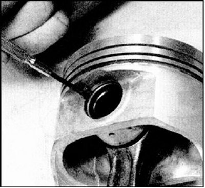
8. Check clearance between piston ring and piston groove wall. To do this, insert the ring from the outside into the corresponding groove and use a feeler gauge to measure the gap between the upper surface of the ring and the groove wall. If even with a new ring the clearance exceeds the norm, then replace the piston.
9. Check the clearance at the junction of the piston rings, for which insert the ring into the corresponding cylinder and push it through the piston head to prevent the ring from being distorted during measurement. Push the ring to such a depth at which the edge of the piston skirt is aligned with the split plane of the cylinder block, then remove the piston. Measure the gap with a feeler gauge. If the gap exceeds the norm, then replace the rings and repeat the procedure. If the gap exceeds the norm and with new rings, then the cylinder should be bored and honed.
10. Carefully check for cracks on the piston skirt, on the piston pin bosses and in the areas between the piston ring grooves.
11. Check the presence of chips and burrs on the rubbing area of the surface of the piston skirt, traces of burning along the edges of the bottom. If chips and scuffs are observed, then this indicates frequent overheating of the engine, one of the reasons for which may be abnormal combustion of the fuel mixture. In this case, a thorough check of the lubrication and cooling systems is required. Traces of melting on the side surface of the piston indicate a breakthrough of gases from the combustion chamber. Piston head burning or burnt areas along the bottom edges indicate abnormal engine operation due to incorrect ignition timing (too early ignition), or due to detonation. If these flaws are found, then their cause must be found and eliminated, otherwise the manifestation of the causes of such wear is possible in the future. The reasons for the abnormal operation of the engine may be air leakage on the intake manifold, incorrect ignition timing, failure of the fuel injection system.
12. Piston corrosion in the form of small pits (pitting) indicates penetration into the combustion chamber (as well as in the crankcase) coolant. Here again, it is required to find the cause and eliminate it, otherwise corrosion will appear on the repaired engine.
13. Carefully inspect the connecting rods for damage such as cracks in the heads near the piston pins and where the connecting rod bearings are installed. Check if there is deformation of the connecting rod body (twist or bend). Damage to the connecting rods is unlikely and only occurs in cases of engine seizure or severe overheating. A thorough check of the connecting rods can only be carried out at the dealer's car service workshop, or at a specialized workshop where the necessary equipment is available.
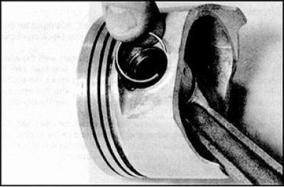
14. If necessary, the piston can be removed from the connecting rod and assembled with the connecting rod as follows: using a flat-blade screwdriver, remove the piston pin circlips and push out the piston pin, if necessary, rest the piston and knock out the finger with hammer blows on the perforator. At the same time, do not damage the holes in the piston and connecting rod for the piston pin.
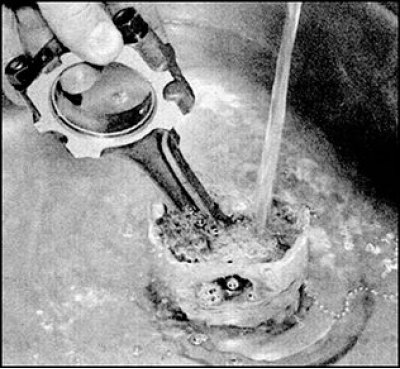
15. Removing the piston pin is greatly facilitated if the piston is preheated to a temperature of 60-70°C. Dip the piston in hot water, remove and squeeze out the piston pin, being careful to avoid injury.
16. Mark the piston, connecting rod and pin so that you can later assemble all the parts together. Retaining rings replace without fail.
17. Check the piston pin and connecting rod bore for signs of wear or damage. If the correct measuring tool is available, the piston and connecting rod clearance can be determined by direct measurements of the pin and bore diameters.
18. If the connecting rod bushing and piston pin are badly worn, or if the pin clearance in the connecting rod head is excessive, then the pin and bushing should be replaced. Replacing the connecting rod head bushings must be done in a workshop, as a press will be needed to remove them and ream the new pressed bushings.
19. If the clearance between the piston and the pin is significantly greater than the norm, then the piston and pin should be replaced as a set. Keep in mind that the clearance between the piston and the pin is not as significant as the clearance in the connecting rod head, since the pin is secured with circlips.
20. The connecting rods themselves do not require replacement, except in cases of engine jamming, or other serious breakdowns. Check the condition of the connecting rods by inspection, if deformation of the connecting rods is detected, take them to a car service workshop for inspection and repair by an experienced specialist.
21. Check the condition of all parts, if necessary, purchase new ones by contacting the dealer's car service.
22. Orient the piston and connecting rod so that the mark on the part of the piston that should be facing the front of the engine (in the form of an arrow or a dash) correctly located relative to the lubrication hole in the body of the connecting rod (see fig. Correct mutual orientation of piston and connecting rod). With the correct mutual orientation, the mark on the piston should be facing the timing chain, and the lubrication hole in the connecting rod body should be facing the rear of the cylinder block.
23. Lightly lubricate the piston pin with fresh engine oil, insert the piston pin into the holes in the piston and in the connecting rod head.
Attention! In order to facilitate the installation of the piston pin, it is recommended to heat the piston.
24. If necessary, put your finger in place with light blows of the hammer on the perforator, having previously fixed the piston.
25. Check for freedom of rotation of the pin in the piston bosses, then install the circlips. Make sure the circlips fit into the grooves next to the piston pin holes.