Removing
1. Remove oil pan, chain (or chains) and flywheel.
2. Remove the piston rods.
Attention! If no repair work is carried out with the pistons and connecting rods, then there is no need to remove the cylinder head and the connecting rod and piston group. The pistons should only be pushed towards the combustion chambers to move a sufficient distance from the crankshaft bearings.
3. Check the end play of the crankshaft, and then perform the following operations.
Engine 2.0L
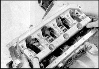
4. Loosen the bolts and remove the left side (flywheel side) cylinder block rear oil seal holder. When loosening the guide pins, remove them and store with the holder.
5. Loosen the main bearing cap bolts 1 turn at a time. After unscrewing the bolts, remove them from the cylinder block.
6. Remove the cast cage from the main bearing caps, paying attention to its orientation.
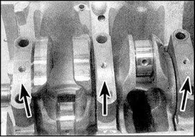
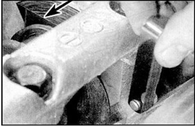
7. Main bearing caps must be numbered 1 to 5 starting with the timing chain cap (the location of the numbering is indicated by arrows). If no numbers are available, apply white paint marks that correspond to the serial number of the cover and determine its orientation in order to prevent incorrect installation of the cover during assembly.
8. Remove the covers and take out the lower shells of the main bearings. Tape each earbud to its respective lid to prevent loss or incorrect insertion of the earbuds.
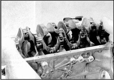
9. Carefully remove the crankshaft, while the displacement of the upper shells of the main bearings is not allowed.
10. Remove the upper main bearings from the cylinder block. Tape each earbud to its respective lid to prevent loss or incorrect insertion of the earbuds. Remove the thrust washers from the middle crankshaft bearing (N3) and store together with the middle main bearing cap.
Checking the end play
1. Axial play is checked before removing the crankshaft from the engine and can move freely in the main bearings (see subsection 3.2.2.11).
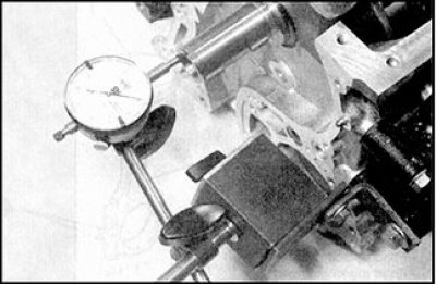
2. Axial play is checked using a dial indicator, which rests against the end of the crankshaft. Move the crankshaft all the way to the side and set the indicator scale to zero. Move the crankshaft in the opposite direction and read the indicator reading. Compare the result with the standard. If the play exceeds the norm, then the thrust half rings will need to be replaced.
3. In the absence of an indicator, axial play can be checked with a feeler gauge. Move the crankshaft all the way to the flywheel side, then measure the play by inserting feeler gauges into the gap between the crankshaft web near the 4th crankpin and the thrust half ring next to the 3rd main bearing.
Status check
4. Wash the crankshaft with kerosene or solvent and dry with compressed air (if available). Thoroughly clean the oil passages inside the crankshaft with a brush.
5. Check the crankpins for signs of uneven wear, cracks, scoring and pitting (fossae).
6. Uneven wear of the connecting rod journal is accompanied by a distinct metallic knock on a running engine (which is especially audible when pressing the throttle pedal while driving at low speed) and a noticeable drop in oil pressure.
7. Wear of the main bearings is accompanied by a strong vibration of the engine and a dull rumbling sound that increases with increasing engine speed, as well as a noticeable drop in oil pressure.
8. Check the roughness of the crankshaft journals by running your finger over them without applying too much pressure. Any roughness (which manifests itself simultaneously with obvious signs of wear of the main and connecting rod bearings) indicates the need for regrinding the crankshaft journals (if possible) or its replacement.
9. Check the runout of the crankshaft in the center using a dial indicator by placing the crankshaft in the prism bearings. If the runout exceeds the norm, then the crankshaft must be replaced.
10. If the crankshaft journals have been ground, deburr around the oil holes (these holes are usually countersunk slightly, so burrs only occur if the grinding work is done carelessly). Burrs are removed with a small needle file or scraper; when finished, carefully clean the holes.
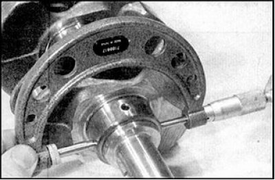 | 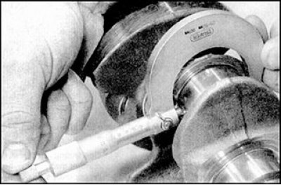 |
11. Measure the diameter of the main (photo on the left) and connecting rod (photo on the right) necks and compare the results with the normative ones from the section (see subsection 3.2.1.1). Determine the ovality of the necks by measuring the diameter at several points around the circumference of the neck. Check the taper by measuring the diameter near the opposite cheeks of the necks. Compare the obtained results with the normative ones.
12. Check up a condition of necks of the crankshaft condensed by epiploons. If there is a deep groove on these necks that has formed in the place of the working edges of the oil seal, then consult a specialist, as either repair or replacement of the crankshaft will be required.
13. The manufacturer supplies repair main and connecting rod bearings as spare parts. For main bearing shells, there is only one repair size (0.25 mm) and three repair sizes for connecting rod bearings (0.08, 0.12 and 0.25 mm). For the purchase of repair main and connecting rod bearings, contact the car service of a Nissan dealer.
14. If repair liners are available for sale, and the wear of the crankshaft journals exceeds the standard so that further repairs are impossible, then it is advisable to purchase a rebuilt crankshaft and install repair bearings. About what actions to take next, consult a car service or a specialist.