Timing drive scheme for DOHC engines
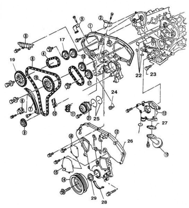
1 - Rear cover of the timing drive; 2 - Front tensioner (left) secondary circuit; 3 - Top guide; 4 - Back (right) secondary circuit; 5 - Rear tensioner (right) secondary circuit; 6 - Main chain tensioner; 7 - Guide of the sagging section of the chain; 8 - Main gas distribution chain; 9 - Crankshaft sprocket; 10 - Lower guide of the main chain; 11 - Top guide of the main chain; 12 - Front cover of the timing drive; 13 - Oil pump; 14 - Crankshaft pulley; 15 - Water pump cover; 16 - Access cover to the chain tensioner; 17 - Asterisks of a secondary chain of final camshafts; 18 - Asterisks of a secondary chain of inlet camshafts; 19 - Asterisks of the main chain of intake camshafts; 20 - Oil filter; 21 - Water pump; 22 - O-rings; 23 - Water drain plug; 24 - Cork; 25 - sealing rings; 26 - O-ring; 27 - Sealing gasket; 28 - Seal; 29 - Front crankshaft oil seal
Attention! Wait until the engine has completely cooled down before proceeding with the procedure.
Removing
1. Disconnect the negative cable from the battery.
Attention! If the stereo system installed in the car is equipped with a security code, before disconnecting the battery, make sure that you have the correct combination to activate the audio system!
2. Support the rear wheels of the vehicle with wheel chocks. Engage the parking brake.
3. Loosen the right front wheel nuts, then jack up the front of the car and place it on jack stands. Remove the wheel.
4. Remove the crankcase protection and the right front wheel arch protection locker.
5. Relieve pressure in the supply system (see chapter Power and exhaust systems). Empty the cooling system (see chapter Settings and ongoing maintenance).
6. Remove the top section of the inlet pipeline (injection chamber) (see Section Removal and installation of the inlet pipeline) and cylinder head covers (see Section Removal and installation of covers of heads of cylinders).
7. Remove the spark plugs (see chapter Settings and ongoing maintenance). Bring the piston of the first cylinder to the TDC position of the end of the compression stroke (see Section Bringing the piston of the first cylinder to the top dead center position (TDC)).
8. Remove drive belts (see chapter Settings and ongoing maintenance) and intermediate roller bracket.
9. Remove the steering pump with bracket (see chapter Suspension and steering).
10. Remove the air conditioner compressor (see chapter Cooling, heating systems).
11. Remove the crankshaft pulley (see Section Removal and installation of the crankshaft pulley).
Note. Do not allow the crankshaft to turn while removing the pulley - the engine must remain in the TDC position of the piston of the first cylinder.
12. Disconnect the electrical wiring from the oxygen sensor, then separate the exhaust pipe from the exhaust manifolds and catalytic converter (see chapter Power and exhaust systems).
13. Hang the power unit from above on a winch or beam.
Attention! Take care of the reliability of mounting the unit!
14. Turn out the through bolts of the front and rear suspension mounts of the power unit and remove the cross beam from the vehicle assembly with the supports fixed to it (see Section Checking the condition and replacing the suspension bearings of the power unit).
15. Remove the bracket for the A/C compressor and the upper and lower sections of the oil pan (see Section Removal and installation of the pallet crankcase of the engine).
16. Through the top, remove the right suspension bracket of the unit (see Section Checking the condition and replacing the suspension bearings of the power unit).
17. Remove the camshaft position sensor from the chain cover (see chapter Engine management systems).
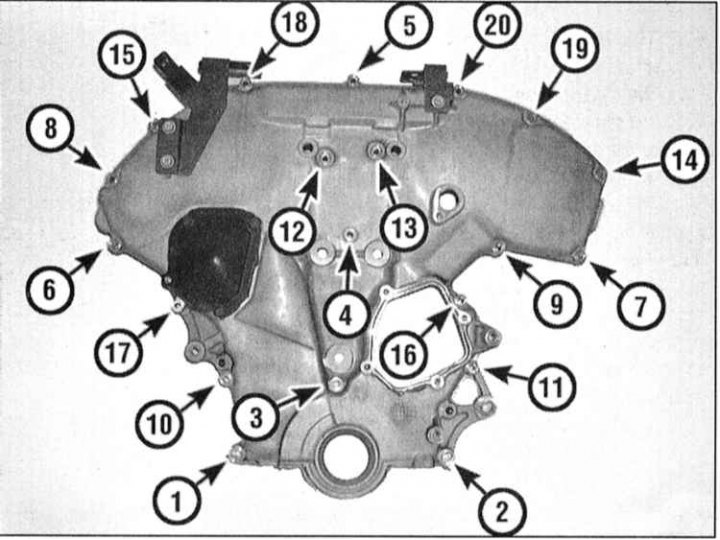
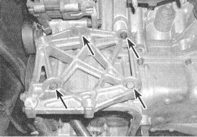
18. Release the wiring harness from the brackets on the top cover of the gas distribution chain. Acting in the reverse order shown in the illustration, remove the front cover mounting bolts. Please note that for fastening the cover, bolts of various sizes are used, which, during assembly, must be installed strictly in their original places - if necessary, make the appropriate marking.
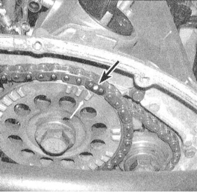
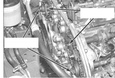
19. On the considered engines (DOHC, 3.0L) the required gas distribution is provided by three circuits. The main chain is worn on the sprockets of the crankshaft, water pump and two intake camshafts and serves to bring the operation of the valve mechanism into phase with the rotation of the crankshaft and the movement of the piston groups. Two secondary timing chains are worn on separate intake camshaft sprockets and exhaust sprockets and serve to synchronize the drive of intake and exhaust valves. Remove the front cover of the timing chain and once again make sure that the piston of the first cylinder is in the TDC position of the end of the compression stroke by the correct location of the alignment marks on the camshaft and crankshaft sprockets relative to the colored chain links.
 |  |
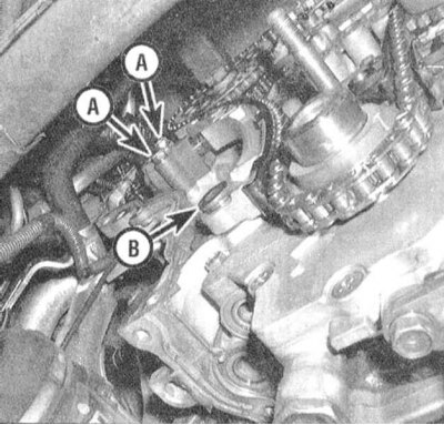
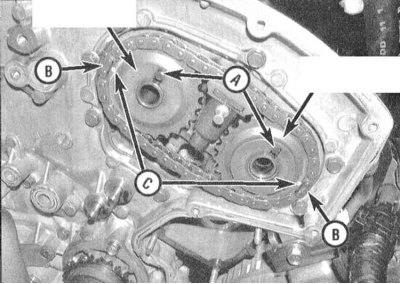
20. To relieve tension on the main timing chain, remove its tensioner and its lever/chain guide.
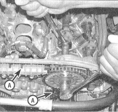
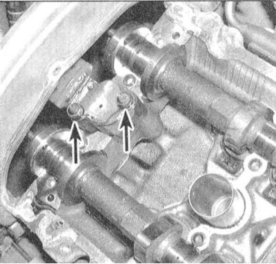
21. Turn out bolts of fastening of the top guides of a chain and bolts of asterisks of the main chain of inlet camshafts.
22. Remove the main chain sprockets from the intake camshaft trunnions.
Note. When installing, the sprockets must be planted on their former shafts - mark accordingly.
23. Wring out the tensioners of the secondary chains and block them by inserting the locking pins into the specially provided holes.
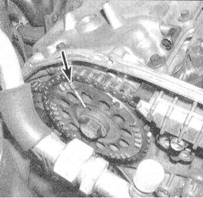
24. Turn out bolts of fastening of asterisks of secondary chains of final camshafts. Make sure that the alignment marks are correctly aligned, then remove both secondary chains with asterisks.
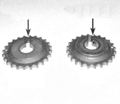
Note. The asterisks of the secondary chains of the intake and exhaust camshafts differ from each other in thickness and must be installed strictly in their original places during assembly - apply the appropriate marking.
 |  |

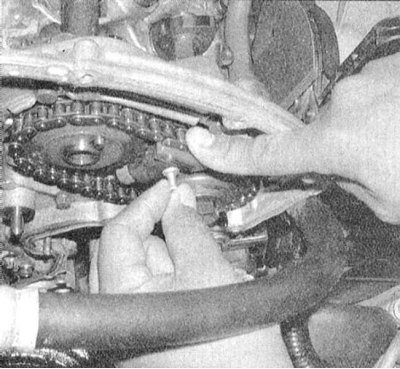
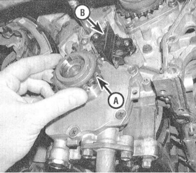
25. Remove the crankshaft sprocket and lower main chain guide.
Examination
Inspect the camshaft sprockets, water pump and crankshaft for signs of worn teeth and keyways, chains for cracks and signs of worn rollers. Assess the condition of the working surfaces of the chain guides.
Note. In order to gain access to the secondary chain guide mounting bolts, the corresponding camshaft journal [corresponding camshaft bearing cap] must be removed from its head in order to gain access to the mounting bolts.
 |  |
Installation
1. Reinstall the crankshaft sprocket and lower main chain guide (mark up).
2. Make sure that the size of the prepared new chains meets the requirements of your car engine - compare them with the old ones. Make sure the location of the colored links matches.
3. If the tensioners of the secondary chains were removed, install them in their places, making sure that the springs are correctly fixed. Place secondary chain assemblies with sprockets on the camshaft trunnions to ensure that the installation methods are aligned correctly. Tighten with the required effort bolts of fastening of sprockets of final shafts.
4. Remove the locking pins from the secondary chain tensioner assemblies.
5. Correctly positioning the colored links relative to the marks on the sprockets, prepare the main gas distribution chain for installation.
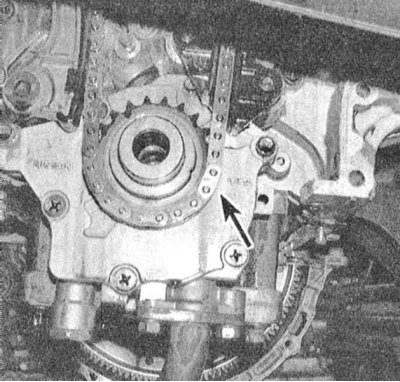
6. Putting the chain on the sprockets of the crankshaft and water pump, install it complete with the remaining sprockets on the engine. Make sure that the light chain link is correctly aligned with the mark on the crankshaft sprocket.
7. Install the upper main chain guides.
8. Install the main chain tensioner arm/chain guide. Make sure the No. 1 piston is still at TDC at the end of the compression stroke and that the colored chain links are not misaligned with the marks on the sprockets.
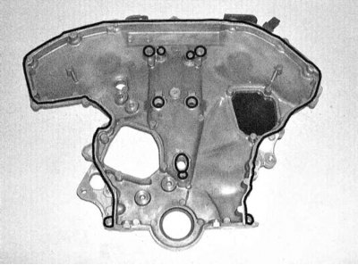
9. Remove all traces of old sealant from the front timing cover and its fastening bolts.
10. Apply fresh RTV sealant to cap. Install the cover on the engine, screw the mounting bolts into place. Moving in a strictly defined order, tighten the fasteners with the required force.

11. Further installation is carried out in the reverse order to the dismantling of the components.