


Table of contents: Removal ↓ Installation ↓
Caution! Wait until the engine has completely cooled down before starting work.
Removal
1. Remove the timing chains with sprockets (see section Removal, condition check and installation of timing chain and sprockets).
Caution! Try not to move the crankshaft out of the TDC position at the end of the compression stroke of the first cylinder.
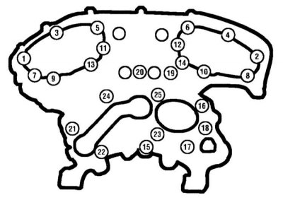
2. Moving in the reverse order to that shown in the illustration, unscrew the bolts securing the rear timing drive cover.
3. Remove the rear timing cover from the engine.
Note. If the cover is "stuck" to any of the heads or to the block, tap it with a hammer through a wooden block. As a last resort, cut the layer of hardened sealant with a putty knife. To avoid compromising the tightness of the component fit, do not attempt to pry the cover under the mating surface with a lever under any circumstances.
4. Remove the lower section of the intake manifold (see section Removal and installation the intake manifold).
5. Remove the camshafts and valve lifters from the cylinder head (see section Removal and installation camshafts and valve lifters).
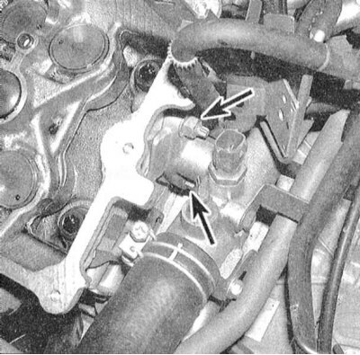
6. Label and remove any remaining components from the head, such as coolant hose connections, tubes, cables, communication lines, etc.
7. Using a rod wrench of the appropriate size, in several steps (1/4 turn per set) gradually loosen the head mounting bolts until they can be unscrewed by hand. To avoid head deformation, loosen the fasteners in the reverse order of tightening.
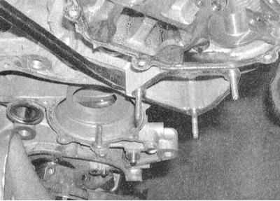
8. Remove the head from the cylinder block. If necessary, carefully pry up a head that is not removable with a pry bar under the casting projection at the level of the mating surface.
9. After removing the external components from the head, prepare it for cleaning and checking its condition.
Note: A description of the cylinder head condition inspection procedure is given in Section General engine overhaul of this Chapter.
Installation
1. The mating surfaces of the head and block must be absolutely clean and dry.
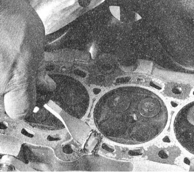
2. After scraping off the remaining gasket material and carbon deposits, wipe the surfaces with a rag soaked in acetone. The presence of traces of oil on the mating surfaces when installing the head can lead to a violation of the seal of the gasket fit and, as a consequence, the development of leaks. When processing the block, plug the cylinder holes with a rag to prevent small debris and various foreign objects from getting into them (as a last resort, vacuum the cylinders thoroughly).
3. Check the mating surfaces of the head and block for deep scratches, burrs, and other damage. Minor defects can be removed with fine-grained sandpaper. In more serious cases, the only alternative is to resurface the components or replace them.
4. Using a tap of the appropriate size, tap the threaded holes for the head mounting bolts. After tapping, blow out the holes with compressed air.
Note: When working with compressed air, do not forget to wear safety glasses!
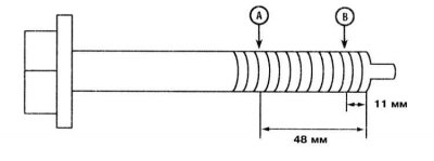
5. Assess the degree of stretching of the fastening bolts. If the difference in diameters measured at the specified points exceeds 0.11 mm, the corresponding bolt must be replaced. Clamping the bolts suitable for further use in a vice by the head one by one, go over their threads with a die - the presence of old sealant, dirt and corrosion products in the threads leads to a discrepancy between the actual tightening force of the fastener and the readings of the torque wrench indicator.
6. Assess the degree of head non-flatness (see Part General engine overhaul of this Chapter). Also check the mating surfaces of the intake manifold and exhaust manifold.
7. Install the removed external components onto the head.
8. Clean the rear timing belt cover and its mounting bolts from traces of old sealant
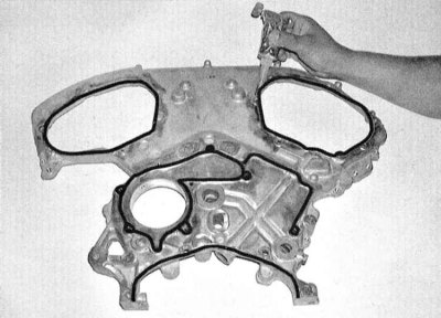
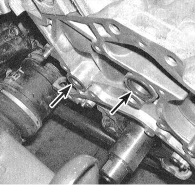
9. Apply fresh RTV sealant to the mating surface of the cover in accordance with the diagram. Insert new sealing rings into the corresponding seats on the front side of the block. Press the rear timing cover onto the guide pins to the surfaces of the block and cylinder heads, then, moving in a strictly defined order, screw in and tighten the mounting bolts to the required force.
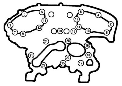
10. Insert the camshafts and valve lifters into the head (see section Removal and installation camshafts and valve lifters). Install the timing chains (see section Removal, condition check and installation of timing chain and sprockets). Further assembly is carried out in the reverse order of dismantling the components.
11. If valve train components were replaced during head maintenance, adjust the valve clearances (see section Checking and adjusting valve clearances).
12. Do not forget to fill the cooling system and replace the engine oil and oil filter (see Chapter Settings and ongoing maintenance).
13. Start the engine and check for signs of oil and coolant leaks. Check the ignition timing (see Chapter Settings and ongoing maintenance).