


Table of contents: Removal and installation ↓ Repair of the main brake cylinder ↓
Removal and installation
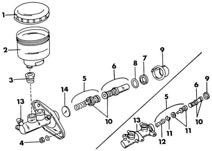
Wiring diagram of the brake master cylinder. The cylinder is shown on the bottom right in the case of ABS installed
1 - lid; 2 - expansion tank; 3 - rubber nozzle; 4 - nut; 1.6 l = 10-15 Nm; 2.0 l = 11-17 Nm; 2.0 l = 8-11 Nm (with ABS); 5 - intermediate piston; 6 - pressure piston; 7 - rubber seal; 8 - intermediate washer; 9 - thrust cap; 10 - piston cuff; 11 - spring cup; 12 - return spring; 13 - cylinder body; 14 - cylinder body gasket
1. Disconnect the cable from the brake fluid level indicator.
2. Unscrew both brake pipes from the cylinder. Plug the ends of the pipes.
3. Loosen the fastening of the master brake cylinder from the end surface of the brake booster and carefully remove the cylinder, without splashing brake fluid on the varnished surfaces. Install the cylinder in the reverse order of removal. After installation, bleed the brake system (Section Bleeding the brakes).
Repair of the main brake cylinder
First, determine the manufacturer of the cylinder. Nissan can have cylinders from different manufacturers. Elements of different designs cannot replace each other. If the ABS system is installed, a different cylinder is installed. The illustration shows both versions of the main brake cylinder.
1. Remove the cap (1) and drain the liquid.
2. Clamp the cylinder in a vice.
3. Using a screwdriver, remove the piston stop cap (9) from the cylinder body. On a cylinder without ABS, bend the two locking tabs on the inside of the flange inwards; on the ABS cylinder, bend the locking tabs outwards from the outside. Then remove the cap.
4. Remove the pressure piston (6). It is possible to use compressed air. Connect the compressed air to the brake hose connection. Wrap the cylinder well with a rag so that the piston does not fly away too far.
5. Check the cap immediately. If one of the locking tabs is damaged, a new cap must be installed.
6. Use your fingers to remove the seals from the piston.
7. If further disassembly is required, carefully pry the expansion tank (2) away from the cylinder using a screwdriver. Remove the rubber cap (3) (always replace).
8. The pressure piston is not disassembled. Clean all parts with brake fluid or alcohol. If the cylinder bore or piston has a satisfactory appearance, measure the bore diameter and the piston outside diameter with a micrometer. The difference between the values should not exceed 0.15 mm.
9. Lower the piston seals into the brake fluid and install them on the piston.
10. When doing this, pay attention to the direction of installation of the cuffs (see illustration below). Reassemble the cylinder according to the assembly diagram. When installing the piston, press both parts into the hole with a screwdriver and install the thrust cap. With the ABS system installed, press the cams inward; without ABS, push the cams outwards. Check that the cap is securely seated on the body.
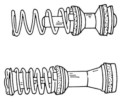
Correct assembly of the intermediate piston (top) and the pressure piston (bottom).