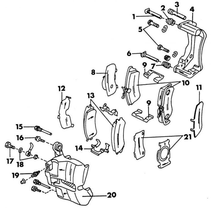
Mounting diagram of disc brakes. Parts marked "*", installed on carburetor models; details marked "**", on injection engines
1 - guide pin **; 2 - rubber cuff **; 3 - rubber cuff *; 4 - caliper holder; 5 - caliper holder bolts, 73-100 Nm; 6 - guide pin **; 7 - rubber cuff **; 8 - inner lining **; 9 - spring plate pads **; 10 - brake pads **; 11 - outer lining **; 12 - inner lining *; 13 - brake pads *; 14 - brake shoe spring *; 15 - guide pin * 3.2-4.2 N·m; 16 - caliper bolt **, 22-33 Nm; 17 - hollow bolt, 17-21 Nm; 18 - copper washers; 19 - bleed valve, 7-13 Nm; 20 - cylinder body; 21 - external pads*
1. Raise the front of the car.
2. Remove wheels.
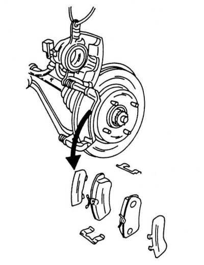
3. On the inside of the caliper, remove the bolt shown in the illustration and tilt the entire caliper up.
4. Remove the top and bottom guide plates, inner and outer brake pads from the caliper. Insert a screwdriver to remove the guide plates.
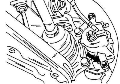
After removing the bolt shown, you can tilt the caliper up. Fasten the caliper with a piece of wire (see illustration).
5. After removing the brake pads, do not press the brake pedal, otherwise the piston will pop out. Replace the brake pads if the thickness of the brake pad material is 2.0 mm. Never replace just one pad or swap brake pads from one side to the other. The illustration below shows where the pad thickness is measured. Brake pads for carburetor models are 10 mm thick, pads for injection models are 11 mm thick. From these dimensions, you can determine the current life of the pad.
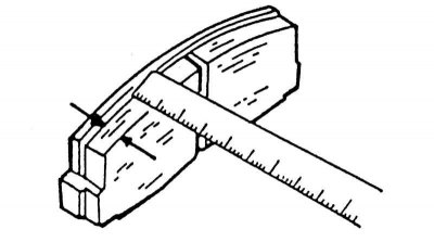
Measuring the thickness of the lining material.
6. Brake pad repair kits include parts that must all be used in installation. Clean the calipers with brake fluid or alcohol. Never use gasoline for this. Check that the piston gaskets seal securely. Check the brake disc for deep grooves caused by worn pads. Measure the thickness of the brake discs with a micrometer as shown in the illustration below. Discs of carburetor models have a minimum allowable thickness of 18 mm, brake discs of injection models (ventilated) have a thickness of 20 mm. If the thickness is less than the specified values, they should be replaced.
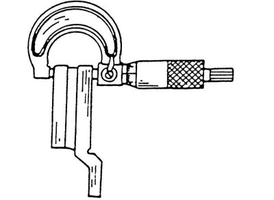
Measuring the thickness of the brake disc.
7. Only one drive can be replaced, but it is likely that both drives need to be replaced. Installing the brake pads is carried out in the reverse order, however, the following points should be noted. The illustration below shows the elements of the caliper, as well as how the caliper cylinder is suspended on a wire:
Elements for removing and installing the brake caliper.
8. Insert the inner pad with intermediate plate, pull the caliper out and insert the outer pad with intermediate plate.
9. Insert the brake shoe guide plates.
10. Untie the wire and lower the caliper cylinder down without damaging the inserted brake pads.
11. Insert bolts (see illustration) and tighten to the tightening torques shown in illustration 2.0. The tightening torques for the two caliper designs are slightly different.
12. After installation several times press a brake pedal and check up, whether air has got into system. If air is in the system, bleed it (Chapter Bleeding the brakes).