Replacement of brake pads
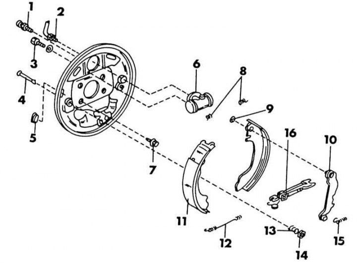
Wiring diagram for rear drum brakes. The big arrow points to the front of the car
1 - bleed valve, 5-8 Nm; 2 - brake pipeline with union nut, 15-18 Nm; 3 - bolt, 6-10 Nm; 4 - anchor pin of the blocks; 5 - cork; 6 - wheel brake cylinder; 7 - bolt, 40-55 Nm; 8 - upper return springs; 9 - lock latch; 10 - shoe lever; 11 - brake pads; 12 - lower return spring; 13 - anchor spring pads; 14 - spring cup; 15 - regulator spring; 16 - pad adjuster
Based on the illustration above:
1. Place the rear of the vehicle on stands. Front wheels must be locked (those bricks), to prevent the vehicle from rolling off the supports.
2. Remove rear wheels.
3. Release the handbrake.
4. Remove the brake drum. If the automatic adjusting device works flawlessly, it is possible that the brake pads will catch on the drum. To loosen the drum, you need to set the adjusting device in the opposite position.
5. To do this, remove the plug from the back of the brake shield in the place shown in the illustration below and insert a screwdriver into the hole as shown in the illustration below. Press the screwdriver inward to release the lever on the inside.
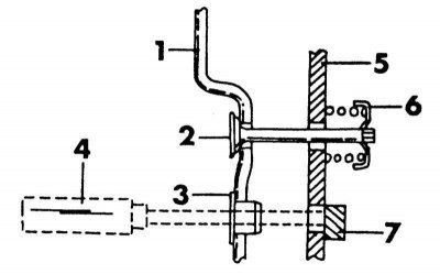
Installation of an automatic adjustment device inside the brake drum
1 - brake shield; 2 - anchor pin of the block; 3 - cork; 4 - screwdriver; 5 - brake shoe; 6 - anchor pin spring; 7 - drive lever
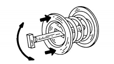
6. Now you need two bolts M8 X 1.25, which are screwed into the places shown in the illustration below. Tighten the bolts evenly until the brake drum is removed.
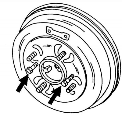
To remove a firmly seated drum by screwing in two bolts in the indicated places.
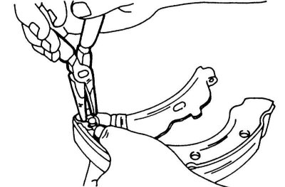
7. Remove anchor pins and springs. To do this, press the pin on the back side of the shield and turn the spring cup on the front side with tongs until the bolt head can pass through the cup. The illustration shows this work clearly. Remove the cup and spring and remove the pin from the back. Thus, remove both pins.
8. Using pliers, unhook the upper return spring from the brake shoes, press the shoes out and remove the adjuster in the middle of the shoes. Remove the lower end of the brake shoe from the counterholder. This releases the lower return spring, which can be removed.
9. Carefully remove the brake pads with the handbrake cable.
10. To do this, compress the spring until the end of the cable can be removed from the lever.
11. If further disassembly is required, unhook the spring from the adjustment lever.
12. When replacing the pads, the lever must be moved to new pads. If the surface of the brake drum is grooved, the drum can be machined until the allowable diameter is exceeded. Also measure the ovality of the drum, especially if the pads overheated when braking. If the material thickness of the brake pads is less than 1.5 mm, the pads must be replaced as a set. Bent springs, also if they were bent during removal, should be replaced. The wheel brake cylinder is described next.
13. Installation of brake pads is carried out in the reverse order of removal. Lightly lubricate the ends of the brake shoes, as well as the places where the shoes fit on the brake shield, and also lubricate the bearing points of the adjusting lever. The adjusting devices must be lubricated on the threaded places of the small wheels and on the connection between the adjuster and the shoe lever, and they must be installed on the old brake shield. Remember the following points:
14. The regulator on the right side has a right hand thread.
15. The regulator on the left side has a left hand thread.
16. If the brake pads have been replaced, install the lever on the brake pads so that it is on the front side and install a new locking latch on the support pin. Insert the latch firmly into the groove, and then, as shown in the illustration below, press it with tongs. Insert the anchor pins and put the springs and spring cups on the front. Rotate the pin heads 90°until the heads lie in the cups.
After installing the retaining ring, press it well into the groove of the support pin.
The illustration below shows schematically how this work is done.
Elements for removing and installing anchor pins for brake pads.
17. After installing the brake pads, you need to set the brakes to auto-adjust. To do this, adjust the adjuster until the diameter of the brake pads approximately matches the diameter of the brake drum. To do this, measure the diameter of the drum and brake pads, as shown on the right and left in the illustration below.
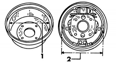
Measuring the brake drum diameter (1) and outer diameter of installed brake pads (2). Set the diameter of the brake shoes 0.35 mm smaller than the diameter of the brake drum.
18. Compare the assembled brake with the illustration below. Regulator head (i.e. expanding rod in the middle) should in any case be closer to the front of the car. Both arrows indicate the direction of rotation of the drum and the front of the vehicle.
19. Put on a brake drum and cock a hand brake several times. Clicks in the brake drum should stop after a while.
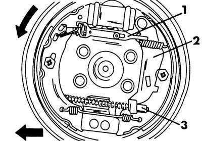
Correct Assembly of the Rear Wheel Brake
1 - regulator; 2 - brake shoe lever; 3 - hand brake cable end
Wheel brake cylinders
To remove the wheel brake cylinder:
1. Remove the brake pads.
2. On the reverse side of the brake shield, loosen the union nut of the brake pipeline.
3. Unscrew the wheel cylinder from the brake shield.
4. Disassembly of the wheel cylinder is not possible, since the control valve installed inside is not subject to repair. If the cylinder is rusted or leaking, it must be replaced with a new one.