


Table of contents: Removal and disassembly ↓ Cleaning and checking the condition…↓ Assembly and installation ↓
Removal and disassembly
1. Jack up the rear of the car and place it on stands. Block both front wheels with wedges.
2. Remove the rear wheel and brake drum.
3. If problems occur, screw two M8 x 1.25mm bolts into the threaded holes in the drum and gradually tighten them while pushing the drum away from the axle flange.
4. To facilitate subsequent assembly, try to remember the installation position of the brake mechanism components.
5. Compress the guide springs of the shoe mounts on the brake shield, turn 90° and remove the holders (spring plates), then remove the springs, spring seats and pins from the brake assembly (the components of the rear wheel drum brake mechanism are shown in the accompanying illustration).
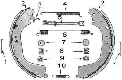
1 - finger; 2 - shoe; 3 - bracket; 4 - upper tension spring; 5 - adjustment bar; 6 - adjusting spring; 7 - saddles; 8 - guide springs; 9 - holders; 10 - lower tension spring
6. Disconnect the lower tension spring from the shoes and the caliper from the brake assembly.
7. Disconnect and remove the upper tension spring.
8. Spread the upper ends of the shoes apart, moving them away from the wheel cylinder pistons, then remove the shoes from the brake shield.
9. Remove the adjusting spring and expansion bar from the shoes.
10. If you are going to replace the shoes, remove the retaining ring and adjusting bracket from the inside of the shoe.
11. Disconnect the brake pipe from the wheel cylinder, loosen the mounting bolts and remove the cylinder from the brake shield.
12. Remove the dust boots, pistons, seals and springs from the wheel cylinder.
Cleaning and checking the condition of components
1. Assess the degree of wear of the friction linings of the brake shoes. If the thickness of the linings is less than the permissible value (see size and adjustment tables at the end of the Manual), they should be replaced or new shoes installed.
2. If the residual thickness of the linings does not exceed the norm, inspect them for traces of contamination with oil or grease; if any are found, replace them.
Note: The pads are replaced in sets of four.
3. Check the brake drums for cracks, scratches, scoring and ovality. If necessary, grind the drums or replace them.
4. Wash the wheel cylinder components with methyl alcohol, then dry them with compressed air.
5. Check the pistons and cylinder bores for cavities and signs of wear. If necessary, hone the cylinder or replace defective components.
Note: On the disassembled wheel cylinder, remove the bleed valve and check its patency. Be sure to replace the rubber dust boots and piston seals.
6. Compare the tensile forces of the return springs of the brake shoes with those of the new ones; replace the springs if necessary.
7. Make sure that the ratchet wheel rotates freely on the adjusting expansion bar. Screw it onto the bar until it stops.
Assembly and installation
Assembly is carried out in the reverse order of disassembly.
1. Lubricate the cylinder mirrors, pistons and seals with clean brake fluid.
2. Put the cuffs on the pistons with the jaws facing inside the cylinder. Make sure that the cuffs are positioned correctly in the piston grooves.
3. Dip the piston and seal assembly into clean brake fluid, then insert it into the wheel cylinder. Make sure that the seal lips do not turn outward during installation. Install the spring and repeat the procedure for the second piston and seal. Put the dust boots on both sides of the wheel cylinder.
4. Install the wheel cylinder on the brake shield. Screw in and tighten the mounting bolts to the required torque.
5. Make sure the brake pipe is clear, then connect it to the wheel cylinder.
6. Where required, install the adjusting bracket and retaining ring on the inside of the shoe and connect the adjusting expansion bar and spring to both shoes.
7. Spread the upper ends of the shoes apart so that they do not catch on the pistons and install the shoe assembly on the brake shield.
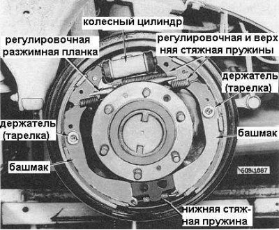
8. Install the pins, seats and guide springs of the brake shoes on the shield. Compress the springs, put on the holders (plates) and turn them to fix the components by 90°. The components of the drum brake mechanism in assembly are shown in the accompanying illustration.
9. Attach the upper and lower tension springs to the shoes.
10. By turning the ratchet wheel of the adjusting expansion bar, bring the shoes together so that they enter the drum with a gap of about 0.25÷0.40 mm.
11. Bleed the hydraulic brake system, install the wheels and lower the vehicle to the ground.
12. Carry out road tests of the vehicle, checking the serviceability of its braking.