


Table of contents: Checking the condition and replacing…↓ Major repair of the caliper ↓ Removal and installation the brake…↓
Note: The following special tools are required to perform the procedures described below: a dial gauge (to check the amount of disk runout), vernier caliper (to measure the thickness of the disc) and a steelyard (for measuring the brake grab force).
Checking the condition and replacing brake pads
1. Jack up the front of the car and place it on supports. Remove the front wheels.
2. Through the viewing window in the caliper body (see accompanying illustration) assess the remaining thickness of the brake shoe friction linings. If the lining thickness of any of the shoes is less than the permissible value (see size and adjustment tables at the end of the Manual), or if the pads are contaminated with grease or brake fluid, all four pads on the brake mechanisms of both wheels should be replaced.
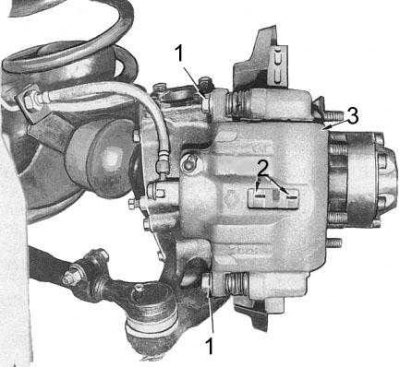
1 - guide pin
2 - pads in the viewing window
3 — support
Note: If the pads are found to be contaminated, the cause of the leaks must also be identified and corrected.
3. Using a syringe, pump out approximately two-thirds of the nominal amount of brake fluid from the master cylinder reservoir.
Note: Used liquid cannot be reused.
4. The purpose of removing the fluid is to prevent it from flowing over the edge of the reservoir when the caliper pistons are pressed in to replace the pads.
Caution: Do not remove all the fluid from the reservoir, as this will require bleeding the hydraulic system.
5. Loosen the lower guide pin bolt and rotate the caliper body up on the upper pin (see accompanying illustration), opening access to the brake pads, adjusting shims and holders in the anchor bracket (guide shoe) calipers.
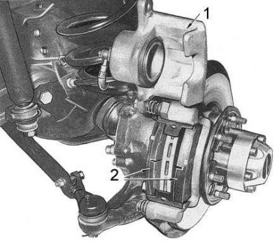
1 — support
2 - pads
6. Note the installation position of the components and remove the holders, pads and adjusting shims from the anchor bracket.
7. Check the adjusting shims and holders for signs of wear and damage. Replace any defective components.
8. Install the adjusting shims onto the pads, then install the pads into their seating positions in the anchor bracket (with gaskets) and holders. Lightly lubricate the holders with silicone grease.
9. Push the piston perpendicularly into the caliper cylinder. Use a clamp if necessary.
10. Make sure the caliper slides freely on the guide pins, then lower it onto the pads.
11. Install the lower guide pin and tighten its bolt to the required torque.
12. After replacing the pads of both brake mechanisms, press the brake pedal several times to seat the pads on the discs. If necessary, add brake fluid to the reservoir to the required level.
13. Install the front wheels and lower the vehicle to the ground.
14. Carry out road tests of the vehicle, checking the proper functioning of the brakes.
Major repair of the caliper
1. Jack up the front of the vehicle and support it. Remove the front wheels. The front disc brake caliper components are shown in the accompanying illustration.
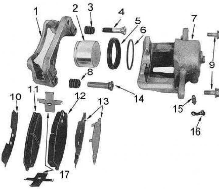
1 - anchor bracket; 2 - piston; 3 - Protective cover of the guide pin; 4 - guide pin; 5 - anther; 6 - piston cuff; 7 - body; 8 - Protective cover of the guide pin; 9 - bolts; 10 - adjusting gasket; 11 - brake shoe; 12 - brake shoe; 13 - adjusting gasket; 14 - guide pins; 15 - bleed valve; 16 - dust cap; 17 - fastening clamps (holders)
2. Loosen the union bolt and disconnect the brake hose from the caliper. Plug the end of the hose to prevent dirt from entering the hydraulic system and to minimize brake fluid loss.
Information obtained from the website nissanbook.ru
3. Loosen the caliper guide pin bolts and remove the caliper body from the anchor bracket assembly.
4. Press a wooden block against the caliper body pad anchors and carefully press the piston out of the caliper cylinder by applying low pressure air to the hydraulic hose mounting hole on the caliper body.
Note: Excessive air pressure may cause the piston to be ejected at high speed, resulting in injury and piston damage.
5. Remove the dust cover from the piston and remove the piston cuff from the cylinder.
Note: To remove the cuff, use a blunt instrument, preferably made of plastic or wood.
6. Remove the guide pins and shoe components from the anchor bracket.
7. Flush the caliper cylinder and piston with clean brake fluid.
8. Check the cylinder bore for cavities, corrosion, wear and damage. Replace the caliper housing if necessary.
Note: Minor defects can be removed with fine sandpaper.
9. Check the piston for cavities, corrosion, signs of wear and damage. Replace if necessary.
Caution: Do not attempt to polish the piston with fine sandpaper as this will damage its lining layer.
10. Check the condition of the shoe components, guide pins and anchor bracket. Replace defective parts.
11. Discard all rubber components removed from the caliper assembly.
12. Lubricate the new piston seal and dust boot with rubber lubricant and install the seal into the cylinder groove. Make sure the seal is seated correctly in the groove - it should not be twisted.
13. Place the dust boot on the piston and lubricate the latter with clean brake fluid.
14. Fully recess the piston into the caliper cylinder and secure the dust boot in the groove on the edge of the cylinder.
15. Lubricate the guide pins and the inside of their protective boots with rubber component lubricant and install the pin assemblies with boots into the anchor bracket.
16. Install the shoe components into the anchor bracket.
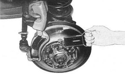
17. Attach a spring balance to the wheel mounting stud and measure the resistance force of the hub to turning (see accompanying illustration). Record the measurement result. If necessary, check the wheel bearing preload adjustment.
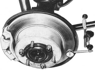
18. Using a dial gauge mounted on a front suspension component with the plunger pressed against the end surface of the brake disc, measure the disc runout (see accompanying illustration). If the measurement result is outside the permissible limits (see size and adjustment tables at the end of the Manual), sharpen the disk or replace it.
19. Using a vernier caliper, measure the thickness of the brake disc at several points along the generatrix. If necessary, grind the disc or replace it.
20. Place the caliper body onto the anchor bracket assembly, screw in and tighten the guide pin bolts to the required torque. Connect the brake hose to the caliper and tighten the union bolt to the required torque.
21. Bleed the hydraulic brake system.
22. Press the brake pedal for five seconds.
23. Release the pedal and turn the front wheel hub ten revolutions.
24. Using a spring balance, measure the resistance force of the hub to turning.
25. Subtract the first measurement from the second measurement to determine the brake grab force. The maximum permissible value is 7.2 kgf, if it is exceeded, find the jammed components and make the necessary repairs.
Removal and installation the brake disc
Removal
1. Remove the front wheel hub assembly.
2. Loosen the mounting bolts and separate the disc from the hub.
Installation
Installation is carried out in reverse order.
1. Tighten the disc mounting bolts to the hub to the required torque.
2. Adjust the wheel bearing preload.