Replacement of brake pads
WARNINGS:
- Do not depress the brake pedal with the cylinder housing open, otherwise the piston will come out.
- Be careful not to damage the piston protector and do not let fluid get on the brake disc.
- If the pad gaskets show signs of corrosion or their rubber coating has begun to flake off, replace the pads.
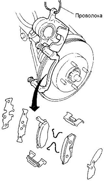
- If the caliper is not replaced and disassembled, there is no need to disconnect the brake hose. Hang the caliper on the wire so that the hose is not under tension.
1. Remove the master cylinder reservoir cap.
2. Remove the bottom guide bolt.

3. Tilt the caliper up. Remove shoe holders, return spring (except for the mechanism of the AD22VF model) and pads.
The commemorative and minimum allowable thickness of the brake linings are given in the section «Data for adjustments and control».
The installation of the pads is carried out in the reverse order.
Watch the liquid level in the reservoir, because when the piston is pressed into the cylinder, the liquid will return to the reservoir.
Checking the brake disc
Beat
1. Secure the disc to the wheel hub with at least two nuts (M12x1.25).
2. Measure the disc axial runout with a dial gauge. First make sure that the axial clearance in the hub bearing lies within the allowable limits (see chapter «Front suspension»).
- The maximum allowable runout is 0.07 mm
3. If the runout exceeds the specified value, try to pick up the position of the disk on the hub, sequentially rearranging it by one hole.
4. If the permutation does not give the desired result, regrind the disc.
Thickness
Measure the disc thickness with a micrometer at 8 points around the circumference. The spread of the measurement results should not exceed 0.02 mm, otherwise the disc must be reground.
Maximum allowable disc thickness:
- CL22VD and CL22VE: - 16.0 mm
- CL22VF - 24.0mm
Assembly
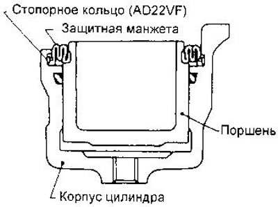
1. Putting a protective cuff on the piston, insert it into the groove of the cylinder, and then install the piston.
2. Secure the cuff with a retaining ring (only in AD22VF model).
Installation
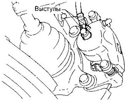
1. Attach a support in gathering to a rotary fist. Attach the brake hose to the caliper, placing it between the tabs (see fig.).
2. Replace all removed parts.
3. Bleed the air from the hydraulic drive (see relevant section of this chapter).