


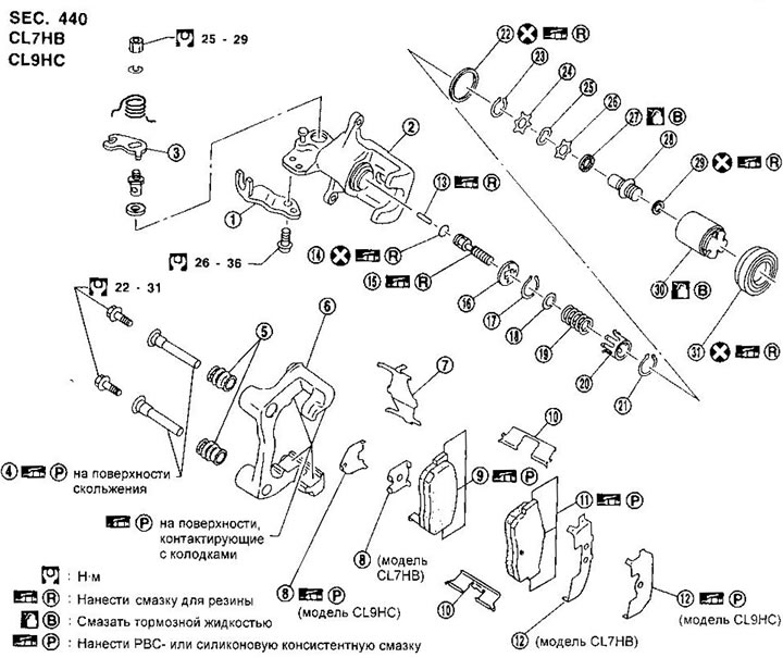
1. Rope guide
2. Caliper
3. The lever of a manual drive of brake pads
4. Guide pins
5. Protective covers for guide pins
6. Shoe guide
7. Holder
8. Inner lining
9. Internal brake pad
10. Shoe holder
11. External brake pad
12. Outer lining
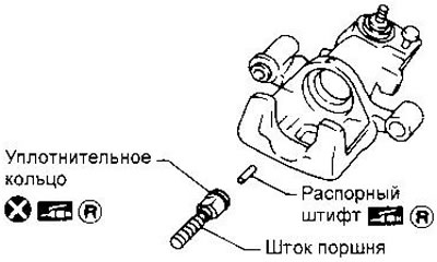
13. Spacer pin
14. O-ring
15. Piston rod
16. Key plate
17. Retaining ring
18. Spring seat
19. Spring
20. Spring cup
21. St support ring
22. Piston O-ring
23. Retaining ring
24. Spacer
25. Spring washer
26. Spacer
27. Bearing
28. Regulator
29. Washer
30. Piston
31. Protective cuff of the piston
Replacement of brake pads
When replacing brake pads, follow all the precautions listed in section «Front disc brake».
1. Remove the master cylinder reservoir cap.
2. Remove the parking brake cable retainer plate.
3. Remove the cable guide from the caliper.
4. Disconnect the parking brake cable.
5. Remove the brake hose retainer plate.
6. Turn away the bottom directing finger.
7. Tilt the caliper forward, then remove the pad holders, inner and outer gaskets, and the pads themselves.
- Nominal thickness of brake pads - 10 mm
- Maximum allowable - 1.5 mm
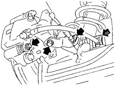
8. When installing new pads, press the piston into the cylinder by rotating it clockwise.
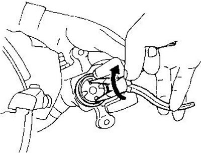
Keep an eye on the level of liquid in the tank, because when the piston is pressed into the cylinder, the liquid will return to the tank.
Removing
1. Remove the parking brake cable retainer plate.
2. Turn away bolts of fastening directing blocks and a connecting bolt of a brake hose.
If the caliper is not replaced and disassembled, there is no need to disconnect the brake hose. Hang the caliper on the wire so that the hose is not under tension.
Disassembly
1. Remove the piston from the cylinder by turning it counterclockwise with needle nose pliers.
2. Remove the circlip from the piston and remove the adjusting nut.
3. Disassemble the cylinder:
- Remove the first circlip and take out the spring cup, spring and seat.
- Remove the second circlip and remove the key plate, piston rod and spacer pin.
- Remove the piston o-ring from the cylinder groove. Be careful not to scratch the cylinder walls.
4. Remove the return spring; lever of manual drive of pads and cable guide.
Caliper check
The test procedure is similar to the front wheel disc brakes.
Checking the brake disc
The test procedure is similar to the front wheel disc brakes.
- Maximum runout - 0.07 mm
Maximum allowable disc thickness:
- CL7HB - 6.0mm
- CL9HC - 8.0mm
Assembly
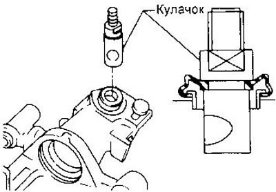
1. Insert the cam, orienting it as shown in the illustration.
2. Lightly lubricate the spacer pin and piston rod with rubber grease to facilitate installation.
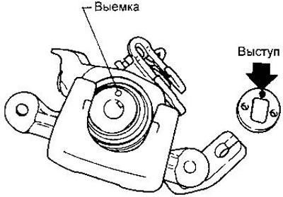
3. Align the tab on the key plate with the notch on the cylinder.
4. Install retaining ring.
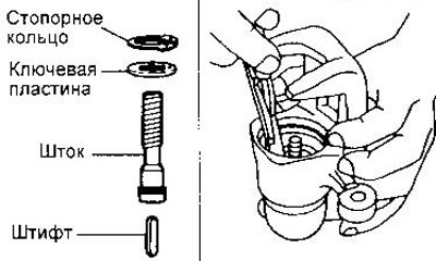
5. Insert planter, spring and spring cup. Then install the second circlip by compressing the spring.
6. Install the regulator as shown.
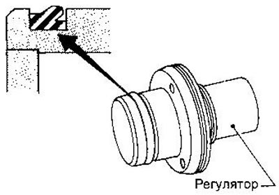
7. Install washer, adjuster, bearing, spacers, and circlip.
8. Insert the piston o-ring into the cylinder groove.
9. With the piston protector on, insert it into the cylinder groove and install the piston by turning it clockwise with needle nose pliers or other suitable tool.
10. Install the hand chock lever, return spring, and cable guide.
Installation
Installation is made in sequence, return to removal. If the caliper has been disassembled, bleed the hydraulic actuator (see relevant section of this chapter).