


Table of contents: Removal ↓ Checking the wheel cylinder ↓ Checking the brake drum ↓ Checking brake pads ↓ Assembly and installation ↓
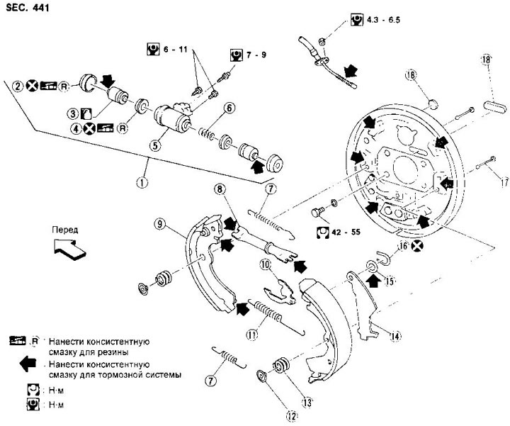
1. Wheel cylinder
2. Protective cap
3. Piston
4. Piston cuff
5. Cylinder body
6. Spring
7. Tension spring
8. Regulator
9. Brake shoe
10. Regulator lever
11. Regulator spring
12. Shoe retainer
13. Pressure spring
14. Hand brake lever
15. Washer
16. Retaining ring
17. Shoe stand
18. Plug
Removal
WARNING: Make sure the parking brake lever is fully released.
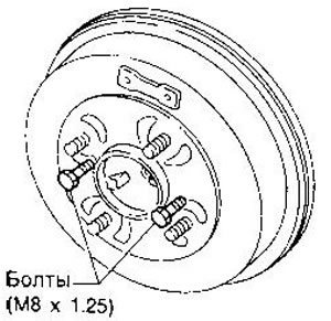
1. Remove the brake drum. If removing the drum is difficult, proceed as follows: Remove the plug, then shorten the adjuster so that there is a gap between the shoes and the drum.
Place two bolts into the drum holes and tighten them until the drum comes off.
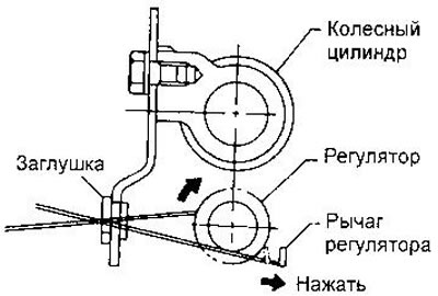
2. After removing the brake shoe retainers, detach the tension spring by turning the shoes.
Be careful not to damage the wheel cylinder protective caps and parking brake cable.
3. Remove the regulator.
4. Disconnect the parking brake cable from the hand brake lever.
5. Disconnect the manual brake shoe lever from the brake shoe by removing the retaining ring with a suitable tool (for example, with a screwdriver).
Checking the wheel cylinder
By visual inspection, make sure there are no brake fluid leaks through the sewn caps. After disassembling the cylinder, check the weight of the internal parts. They should not have any corrosion, signs of wear or damage.
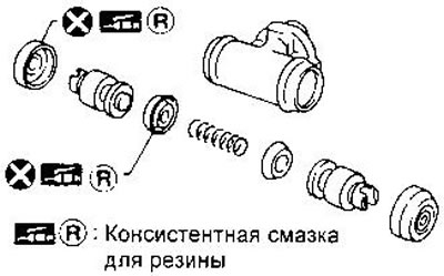
When assembling the cylinder, be careful not to scratch the cylinder walls when installing the pistons.
Checking the brake drum
The working surface of the drum should be treated with sandpaper with a grain size of 120-150.
If there are deep grooves, stepped wear and other defects on the working surface of the drum, bore the drum on a machine.
- Maximum internal diameter - 181 mm
- Maximum ovality - 0.03 mm
Checking brake pads
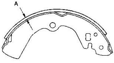
Check the thickness of the brake linings (A).
- Nominal thickness of pads - 4.0 mm
- Maximum permissible - 1.5 mm
Assembly and installation
1. Attach the manual brake shoe release lever and secure it with the retaining ring.
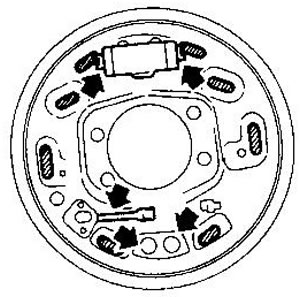
2. Apply brake grease to the areas shown in the figure.
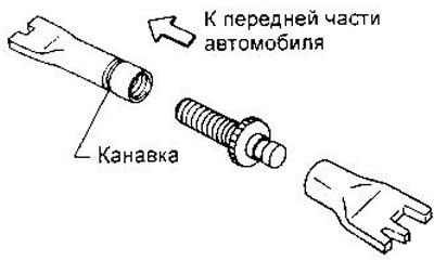
3. Shorten the adjuster as much as possible. Note that the adjusters have different threads: left for the left wheel, right for the right. There is an annular groove pressed into the adjuster of the left wheel.
4. Attach the parking brake cable to the manual brake pad drive lever.
5. Install all remaining parts.
Please pay attention to the direction of installation of the regulator.
Read more on the website (nissanbook.ru)
7. Install the brake drum.
8. When installing a new wheel cylinder or repairing an old one, remove air from the hydraulic drive (see the relevant section of this chapter).
9. Adjust the parking brake (see section "Parking brake drive, Adjustment").