


Car front suspension Nissan Almera 1

General remarks
Final tightening of fasteners when installing rubber suspension parts must be performed on a fully loaded but unloaded vehicle standing on the ground. After installing...
Final tightening of fasteners when installing rubber suspension parts must be performed on a fully loaded but unloaded vehicle standing on the ground. After installing...

Special and standard tools and accessories
Special tools and devices NT72520000 Ball joint and tie rod end puller NT71780000 Suspension Spring Compressor ST35652000 Device for fixing shock absorber struts...
Special tools and devices NT72520000 Ball joint and tie rod end puller NT71780000 Suspension Spring Compressor ST35652000 Device for fixing shock absorber struts...

Checking the suspension parts on the car
General procedures Check suspension components for increased play, wear, cracks and other damage. Rock the front wheels vertically to determine if there is increased...
General procedures Check suspension components for increased play, wear, cracks and other damage. Rock the front wheels vertically to determine if there is increased...

Front suspension device
When installing rubber bushings, final tightening should be performed with the vehicle fully loaded but unladen and on the ground. 1. Suspension crossbar 2. Anti-roll...
When installing rubber bushings, final tightening should be performed with the vehicle fully loaded but unladen and on the ground. 1. Suspension crossbar 2. Anti-roll...

Front wheel alignment angles
Before measuring the front wheel alignment angles, a few preliminary checks must be performed. The vehicle must be fully equipped (filled with fuel, oil and coolant;...
Before measuring the front wheel alignment angles, a few preliminary checks must be performed. The vehicle must be fully equipped (filled with fuel, oil and coolant;...

Hub and steering knuckle — device
1. Drive shaft 2. Inner mudguard ring 3. Steering knuckle 4. Protective cover 5. ABS sensor 6. Wheel bearing 7. Retaining ring 8. Outer mudguard ring 9. Wheel mounting...
1. Drive shaft 2. Inner mudguard ring 3. Steering knuckle 4. Protective cover 5. ABS sensor 6. Wheel bearing 7. Retaining ring 8. Outer mudguard ring 9. Wheel mounting...

Hub and steering knuckle — removal and installation
Removal CAUTION: Before removing the steering knuckle and hub, disconnect the ABS sensor and set it aside. Otherwise, the sensor wires may be damaged, causing the sensor...
Removal CAUTION: Before removing the steering knuckle and hub, disconnect the ABS sensor and set it aside. Otherwise, the sensor wires may be damaged, causing the sensor...

Hub and steering knuckle — disassembly and assembly
Disassembly CAUTION: After pressing the hub or bearing out of the steering knuckle, always replace the bearing assembly (outer ring, inner ring and mudguard rings). Hub...
Disassembly CAUTION: After pressing the hub or bearing out of the steering knuckle, always replace the bearing assembly (outer ring, inner ring and mudguard rings). Hub...

Drive shaft parts (GA and CD engines)
1. External constant velocity joint 2. Protective case 3. Protective cover clamps 4. Retaining ring 5. Drive shaft 6. Dynamic damper clamps 7. Dynamic damper 8....
1. External constant velocity joint 2. Protective case 3. Protective cover clamps 4. Retaining ring 5. Drive shaft 6. Dynamic damper clamps 7. Dynamic damper 8....

Drive shaft parts (SR20DE engine)
1. External constant velocity joint 2. Protective cover clamps 3. Protective case 4. Retaining ring B 5. Drive shaft 6. Dynamic damper clamps 7. Dynamic damper 8....
1. External constant velocity joint 2. Protective cover clamps 3. Protective case 4. Retaining ring B 5. Drive shaft 6. Dynamic damper clamps 7. Dynamic damper 8....

Drive shaft — removal and installation
Removal 1. Loosen the drive shaft nut. There is no need to remove the brake caliper. Do not twist or stretch the brake hose when moving parts. 2. Remove the bolts...
Removal 1. Loosen the drive shaft nut. There is no need to remove the brake caliper. Do not twist or stretch the brake hose when moving parts. 2. Remove the bolts...

Drive shaft — disassembly, inspection and assembly
Disassembly The drive shaft parts are shown in here and here . From the gearbox side (types TS70C, TS79C, TS83): 1. Remove the clamps from the protective cover. 2....
Disassembly The drive shaft parts are shown in here and here . From the gearbox side (types TS70C, TS79C, TS83): 1. Remove the clamps from the protective cover. 2....

Front suspension parts
1. Remote laying 2. Rubber element of the upper support of the rack 3. Upper support of the telescopic stand 4. Thrust bearing 5. Upper spring cup 6. Upper spring...
1. Remote laying 2. Rubber element of the upper support of the rack 3. Upper support of the telescopic stand 4. Thrust bearing 5. Upper spring cup 6. Upper spring...

Telescopic strut and spring
Removal and installation Loosen the bolts and nuts securing the telescopic stand (on the steering knuckle and under the hood). Do not loosen the shock absorber rod nut...
Removal and installation Loosen the bolts and nuts securing the telescopic stand (on the steering knuckle and under the hood). Do not loosen the shock absorber rod nut...

Transverse stability stabilizer
Removal and installation When installing, ensure that the mark on the stabilizer bar is correctly positioned relative to the mounting bracket. When removing and...
Removal and installation When installing, ensure that the mark on the stabilizer bar is correctly positioned relative to the mounting bracket. When removing and...
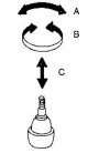
Lower arm and ball joint
Removal and installation 1. Loosen the drive shaft nut. 2. Disconnect the steering rod from the steering knuckle. 3. Loosen the bolts securing the telescopic strut to...
Removal and installation 1. Loosen the drive shaft nut. 2. Disconnect the steering rod from the steering knuckle. 3. Loosen the bolts securing the telescopic strut to...

Data for adjustments and control
Front wheel alignment angles* * For a fully equipped but unladen vehicle. ** In models with power steering, measured at idle with a steering wheel rim force of 98 to 147...
Front wheel alignment angles* * For a fully equipped but unladen vehicle. ** In models with power steering, measured at idle with a steering wheel rim force of 98 to 147...
This section is available on: russian, bulgarian, belarusian, ukrainian, serbian, croatian, romanian, polish, slovak, hungarian
Similar information for other Nissan models
➜ Chassis: Front suspension Nissan Serena 2 (1999-2005)
➜ Chassis: Front suspension Nissan X-Trail 2 (2007-2013, petrol)
➜ Chassis: Front suspension Nissan Murano 1 (2002-2007, petrol)
➜ Chassis: Front suspension Nissan Primera 1 (1990-1996, petrol)
➜ Chassis: Front axle and suspension Nissan Patrol 4 (1987-1997, petrol)
Link in different formats to this section
TEXTHTMLBB Code
- User manual
- Control devices
- Preparing to move
- Heating, air conditioning and audio
- Starting the engine and driving
- Maintenance
- Technical information
- Power unit
- Engine repair
- Lubrication system
- Cooling system
- Control system (gasoline)
- Control system (diesel)
- Power and exhaust system
- Transmission
- Clutch
- Manual gearbox
- Automatic gearbox
- Chassis
- Front suspension
- Rear suspension
- Steering
- Brake system
- Body
- Heating and air conditioning
- Safety system
- Body elements
- Electrical equipment
- Equipment and devices
- Power devices
Cookies are used to improve the site's performance. 💻 Continue by agreeing to the terms.