After the ignition is turned on, the system performs a self-test and the ABS warning light comes on for 1 second. When the vehicle reaches 6 km/h for the first time, the system performs a second test. Mechanical noise may be heard during this, which is normal. If a malfunction is detected during this test, the ABS warning light will come on.
Mechanical noise may be heard during operation of the anti-lock braking system. This is not a malfunction.
Hydraulic circuit
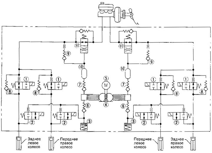
1. Inlet solenoid valve
2. Exhaust solenoid valve
3. Reservoir
4. Pump
5. Pump motor
6. Inlet valve
7. Exhaust valve
8. Bypass valve
9. Check valve
10. Receiver
11. Gradient switch
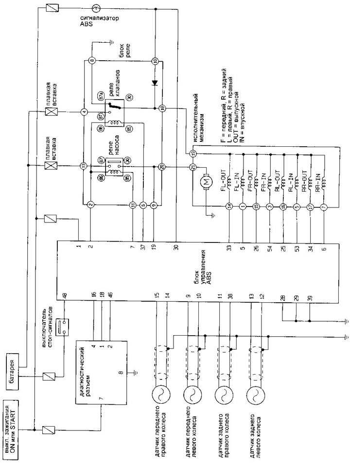
Circuit diagram
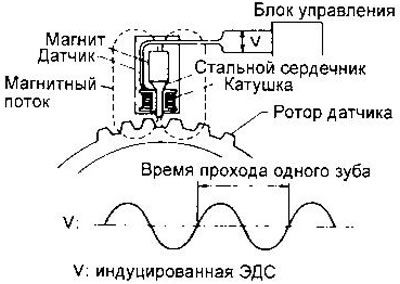
Wheel speed sensors
These sensors provide information on the basis of which the ABS control unit generates all control signals. The sensor is a magnet with a coil wound around it. When passing by the core of the rotor teeth coil, installed on the rear side of the brake disc, a sine-shaped EMF is induced in the coil. The frequency and amplitude of the sinusoid increase as the wheel speed increases.
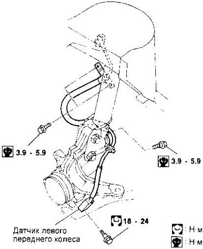
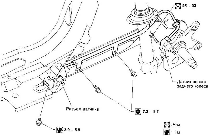
Spotting and sensor installation. Be careful not to damage the edge of the sensor and the teeth of the rotor. When removing the front or rear wheel hub, disconnect the ABS sensor and move it to the side.
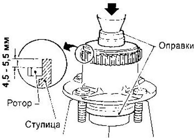
Removal and installation of the rotor. You must first remove the drive shaft or rear wheel hub (see chapters «Front suspension and front wheel drive», «Rear suspension»). To remove the rotor, use a suitable puller and mandrel. Use a hammer and a piece of wood as a spacer to press the rotor onto the drive shaft. When pressing the rotor onto the rear wheel hub, observe the distance shown in the figure on the right.
Sensor test. Measure the resistance between the sensor connector pins. It should lie in the range of 0.8-1.2 kOhm. Check for damage to the sensor tip and rotor teeth. The gap between the sensor and the rotor should be 0.1-1.1 mm.
Control block
The ABS control unit calculates the wheel speed from the sensor signals and directly controls the operation of the actuator solenoid valves, as well as turns on and off the valve and pump motor relays. If a malfunction is detected in the electrical circuits, the malfunction indicator turns on and the system is put into a non-working state. The braking system works in the same way as without ABS.
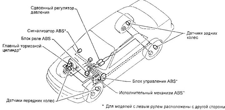
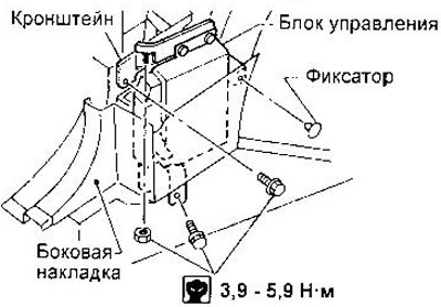
The control box is located on the passenger side behind the instrument panel side trim.
Actuating mechanism
The actuator contains inlet and outlet valves for the brake mechanisms of each wheel, as well as a pump driven by an electric motor.
The figure shows the mounting of the actuator in left hand drive models. In right-hand drive models, the mount is generally similar.
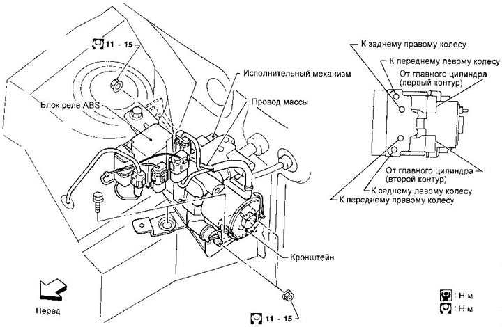
Removal of the actuator is carried out in the following sequence:
1. Disconnect the wires from the battery.
2. Drain the brake fluid.
3. Discharge the air conditioning system.
4. Disconnect all connectors from the ABS relay bracket.
5. Turn away a bolt of fastening of an arm of the relay.
6. Remove the relay box along with the bracket. Remove the air conditioner low pressure lines.
8. Disconnect the brake lines from the actuator (it is not necessary to remove the pipelines from the car).
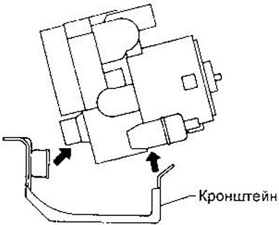
9. Turn away nuts of fastening of the executive mechanism to an arm.
10. Remove the actuator as shown.
Installation is carried out in reverse order.
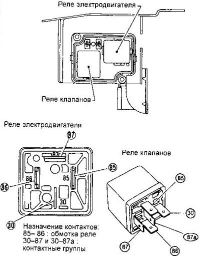
Actuator relay
To access the relay, remove the cover of the relay box.
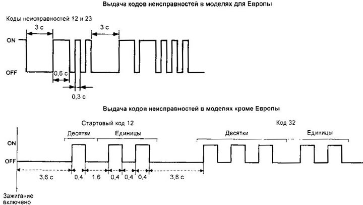
Self-diagnosis
Models for Europe. To issue self-diagnosis results, the ABS indicator must be driven at a speed of at least 15 km / h for at least one minute, then stop with the engine running. Up to three faults can be stored in the memory of the control unit. To erase the fault codes from the memory, it is necessary to disconnect the control unit connector or the ground wire from the battery for at least one minute.
Fault codes are separated by a pause of 3 seconds. Tens are indicated by long flashes (0.6 s), units short (0.3 s).
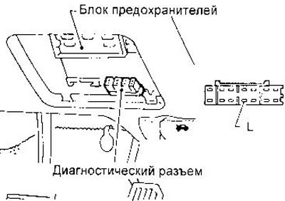
Models outside of Europe. To switch to the self-diagnosis mode, it is necessary to turn off the ignition, short the contact L of the diagnostic connector to ground with a suitable conductor and turn on the ignition. The brake pedal must not be depressed. After 3.6 sec. the ABS warning light will flash, indicating a fault code.
The indication stops after 5 minutes. However, after the ignition is switched off and then on again, the display will resume.
To switch to normal operation, disconnect terminal L from ground and turn off the ignition.
To erase fault codes, disconnect contact L from ground (the signaling device will remain a handful) and then short it to ground 3 times within 12.5 seconds. The duration of each closure must be at least 1 second. After erasing is completed, the indicator will turn off.
To check the system after repair, drive at a speed of at least 30 km/h for at least one minute. The ABS warning light should not come on.
Fault codes
| Code | Faulty element |
| 45 | Front left exhaust valve |
| 4ft | Front left intake valve |
| 41 | Front right exhaust valve |
| 42 | Front right inlet valve |
| 51 | Rear right exhaust valve |
| 52 | Rear right inlet valve |
| 55 | Rear left exhaust valve |
| 56 | Rear left intake valve |
| 25 | Front left sensor (cliff) |
| 26 | Front left sensor (closure) |
| 21 | Front right sensor (cliff) |
| 22 | Front right sensor (closure) |
| 35 | Rear left sensor (cliff) |
| 36 | Rear left sensor (closure) |
| 31 | Rear right sensor (cliff) |
| 32 | Rear right sensor (closure) |
| 18 | Sensor rotor |
| 61 | Electric motor or its relay |
| 63 | Valve relay |
| 57 | Power supply (low voltage) |
| 71 | Control block |
If the ABS indicator does not go out after the ignition is turned on, there may be malfunctions in the power supply circuit of the control unit, in the signaling device circuit, in the control unit or its connector, in the power supply circuit of the valve relay winding or in the hall and panel of the valve relay.
If in the self-diagnosis mode, the signaling device is constantly on or does not turn on, the control unit is faulty.
If the indicator does not illuminate when the ignition is turned on, check the fuse, indicator lamp and its circuit. It is also possible that the control unit is faulty.