Hydraulic diagram of the anti-lock brake system
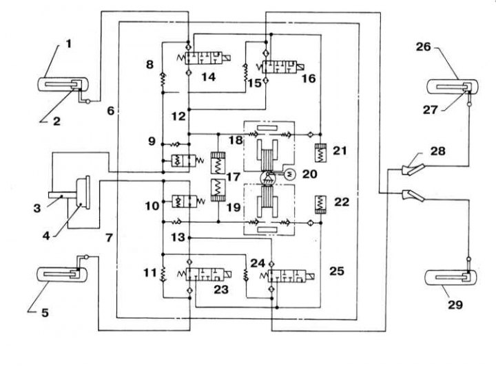
1 - Right front wheel; 2 - Brake caliper; 3 - GTZ; 4 - Assembling the vacuum brake booster; 5 - Left front wheel; 6 - Secondary part of the circuit; 7 - Primary part of the contour; 8 - Left front control valve; 9 - Secondary sensitive valve; 10 - Primary sensitive valve; 11 - Right front control valve; 12 - Secondary drain valve; 13 - Primary drain valve; 14 - Right front solenoid valve; 15 - Control valve; 16 - Right rear solenoid valve; 17 - Hydraulic accumulator; 18 - Pump; 19 - Pump; 20 - Drive electric motor; 21 - Reservoir; 22 - Reservoir; 23 - Left front solenoid valve; 24 - Control valve; 25 - Left rear solenoid valve; 26 - Right rear wheel; 27 - Brake caliper; 28 - Load-sensing control valves; 29 - Left rear wheel
General information
When the vehicle is equipped with a conventional brake system, depressing the foot brake pedal suddenly causes the wheels to lock. In this case, the grip of the tread with the road surface is disturbed, and the car can go skidding, losing controllability. Anti-lock brake system (ABS) prevents premature blocking of the wheels by continuously controlling the speed of their rotation during braking by modulating the pressure of the hydraulic fluid in each of the brake mechanisms.
ABS consists of two main subsystems: electrical and hydraulic. The electrical part of the system includes four wheel speed sensors, an electronic control unit (ECU) and a set of connecting wiring. The hydraulic part includes a pressure modulator, disc brake calipers and hydraulic lines connecting the listed components.
The principle of operation of the system is quite simple. Each of the wheels is equipped with an individual speed sensor. The sensor consists of a rotor (rings with teeth evenly spaced around its perimeter) and a sensitive element in the form of a magnetized coil. The sensitive element of the sensor captures the moment when the teeth of the rotor pass by it and converts the information received into electrical signals that are continuously transmitted to the ABS ECU. Based on the results of processing the incoming signals, the control unit receives information about the relative speed of rotation of each of the wheels. As long as all four wheels rotate at the same speed, ABS is in a passive state. As soon as any of the wheels begins to lock up, the ECU detects a change in the input signal and issues a command to operate a modulator that instantly relieves hydraulic fluid pressure in the brake mechanism of the corresponding wheel. As soon as normal rotation of the wheel is restored, the processor suspends the functioning of the modulator.
In reality, the ABS operation is much more complicated than it might seem, so the compilers of this manual do not recommend car owners to attempt to repair the system on their own. In the event of a problem, it would be wiser to contact a car service specialist. For reference, the illustration shows a functional diagram explaining the principle of operation of the ABS hydraulic part.
ABS components
Pressure modulator
The modulator consists of an electrically driven hydraulic pump, and three solenoid switch valves (two left and right front and rear). An electric pump supplies hydraulic fluid to the reservoirs and a modulator that controls the process of pressure changes in the brake circuits. The pump is placed in a common casing with a modulator assembly. Solenoid valves-switches play the role of actuators that actually provide the required pressure modulation in the hydraulic path of the brake system during ABS operation.
Wheel sensors
Special sensors that are equipped with the wheels of a car, when the teeth of rotating rotors pass by their sensitive elements, generate a frequent comb of electrical impulses. The analog amplitude signal of the corresponding parameters is fed to the control unit (ECU) ABS, which converts it to digital form and, based on the analysis of the received information, determines the speed of each of the wheels.
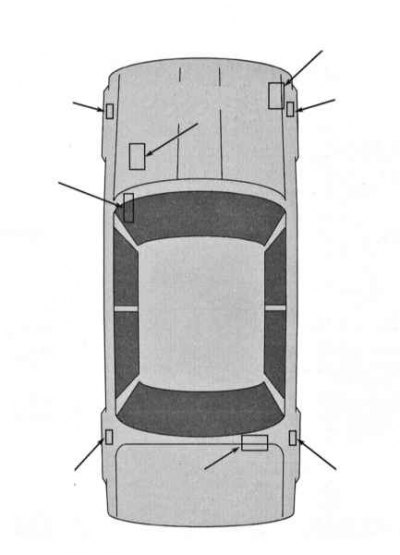
The front wheel sensors are mounted on the steering knuckles in close proximity to the rotors pressed into the outer CV joint assemblies.
The rear wheel sensors are bolted to the hub assembly holders while the rotors are built into the hubs.
Electronic control unit (ECU) ABS
The electronic control unit, often referred to as the processor, is installed in the luggage compartment of the vehicle (1993 and 1994 models issue), or under the front sill of the driver's door (models since 1995 issue.). The ECU, playing the role of the brain center of the system, receives information from the wheel sensors and, based on its analysis, controls the pressure modulations in the hydraulic paths of the brake mechanisms of each of the wheels, preventing their premature blocking. The processor continues to function during the normal movement of the vehicle, constantly monitoring the condition of the ABS components.
Each time the engine is started, the ABS warning lamp in the vehicle's instrument panel comes on briefly. The first diagnostic poll of the status of the ABS components is made by the control unit when the vehicle speed reaches 6.4 km/h (4 mph). interrogation may be accompanied by a faint mechanical sound, which should not be given importance. In the event of a malfunction, the ECU ensures that the ABS warning lamp is turned on, at the same time the corresponding fault code is entered into the processor memory, the reading of which will later determine the source of the failure.
Diagnostics and refurbishment
When the processor detects a problem in the system, the ABS warning light in the instrument panel lights up and remains on. Diagnosing malfunctions of the anti-lock braking system is one of the rather complex procedures and the compilers of this Guide do not recommend doing it at home. Nevertheless, a number of simple checks can be distinguished, which can be quite successfully carried out on their own by the owner of the car and make it possible to qualitatively determine the cause of the failure (see below).
Models 1993 and 1994 issue
- a) Accelerate the car up to 32 km/h (20 mph) and maintain this speed for at least one minute;
- b) Stop driving, but do not turn off the engine;
- c) Open the luggage compartment and count the number of flashes of the control unit mounted in the assembly (ECU) ABS warning light on LED. If there are fault codes in the processor memory, the control lamp will give out a series of continuous flashes with pauses of 5-10 seconds between them;
- d) The decoding of the codes displayed by the control lamp is given in the explanatory map (see below).
- e) Stop the engine.
Models since 1995 vol.
- a) Accelerate the car up to 32 km/h (20 mph) and maintain this speed for at least one minute;
- b) Stop driving and turn off the engine;
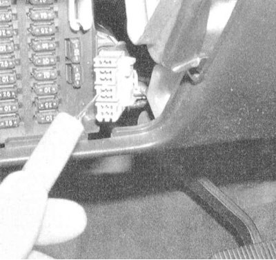
- c) Ground terminal L of the DLC diagnostic connector;
- d) Turn the ignition key to the ON position;
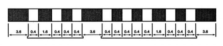
- e) After 3.6 seconds, the ABS warning lamp will begin to flash two-digit system fault codes stored in the processor's memory. Each digit of the code is identified by a series of short (by 0.4 seconds) flashes of the lamp, separated by pauses of the same duration, the second digit is separated from the first by a pause of 1.6 seconds. The moment of the start of reading is marked by the issuance of code 12 (one flash, pause, two flashes). Then again follows a long (3.6 seconds) a pause after which the lamp starts to flash the codes stored in the memory of the control unit.
- f) The decoding of the codes displayed by the control lamp is given in the explanatory map (see below).
The reason for entering the code into the processor memory can be the simplest malfunction - first of all, make the following checks:
- a) Make sure the hydraulic fluid level in the GTZ reservoir is correct;
- b) Check the condition of the contact connections of the relevant electrical circuits;
- c) Check the condition of the fuses;
- d) Check the condition of the brake system (see chapter Settings and ongoing maintenance);
- e) Check the condition of the brake pads;
- f) Check the condition of the foot brake pedal.
Clearing ABS memory
To clear the processor memory, disconnect the ground terminal L of the DLC connector - the ABS indicator lamp should remain on. Ground the L terminal three times in succession within 12.5 seconds. Each subsequent grounding must last at least 1 second longer than the previous one, - the pilot lamp must turn off:
- a) If the control lamp remains on after the earthing of the terminal, drive the car to a service station for more detailed diagnostics and the necessary ABS repair;
- b) If the lamp goes off, drive the vehicle for a short period of at least 1 minute at a speed of 32 km/h (20 mph) and check that the lamp does not flash again. If the lamp turns on again, drive the car to a service station for diagnostics and ABS repair.
ABS fault code map for 1993 and 1994 models issue
| Number of flashes, LED | Presumably faulty light emitting unit or circuit |
| 1 | Solenoid valve-pressure switch in the path of the left front wheel |
| 2 | Solenoid valve-pressure switch in the path of the right front wheel |
| 3 | Solenoid valve-pressure switch in the path of the right rear wheel |
| 4 | Solenoid valve-pressure switch in the path of the left rear wheel |
| 5 | Left front wheel speed sensor |
| 6 | Right front wheel speed sensor |
| 7 | Right rear wheel speed sensor |
| 8 | Left rear wheel speed sensor |
| 9 | Electric motor and relay of its inclusion |
| 10 | Solenoid valve enable relay |
| 16 (or continuous light) | ECU |
| ABS warning light on, LED off | Ground or ECU power supply circuit |
Ground or ECU power supply circuit
| The number of flashes given by the LED | Suspected faulty node or circuit |
| 12 | Starting time to read codes |
| 16 | Brake light circuit |
| 18 | wheel sensor rotor |
| 21 | Open in the right front wheel speed sensor circuit |
| 22 | Short circuit in the right front wheel speed sensor circuit |
| 25 | Open in the left front wheel speed sensor circuit |
| 26 | Short circuit in the left front wheel speed sensor circuit |
| 31 | An open in the right rear wheel speed sensor circuit |
| 32 | Short circuit in the right rear wheel speed sensor circuit |
| 35 | An open in the left rear wheel speed sensor circuit |
| 36 | Short circuit in the left rear wheel speed sensor circuit |
| 41 | Exhaust valve-switch ABS modulator right front brake mechanism |
| 42 | ABS Modulator Right Front Brake Intake Valve Switch |
| 45 | Exhaust Valve-Switch ABS Modulator Left Front Brake Mechanism |
| 46 | ABS Modulator Left Front Brake Intake Valve Switch |
| 51 | ABS Modulator Right Rear Brake Exhaust Switch |
| 52 | ABS Modulator Right Rear Brake Intake Valve Switch |
| 55 | Exhaust Valve-Switch ABS Modulator Left Rear Brake Mechanism |
| 56 | ABS Modulator Left Rear Brake Intake Valve Switch |
| 57 | Violation of the supply voltage level |
| 61 | Modulator electric motor, or relay for its activation |
| 63 | Violation in the solenoid valve relay circuit |
| 71 | ECU |
| 81 | Engine speed sensor |
| 85 | ECU ABS |
| 87 | The engine is running in emergency mode |
| 92 | LAN transfer start procedure not completed |
| 94 | Reception continues after LAN transmission is completed |
| 96 | LAN is in tracking mode |
| 98 | LAN transmission system failure |
| The control lamp continues to burn after inclusion of ignition | ECU power supply circuit; Control lamp circuit; ECU or its wiring connector; Sticking of the electromagnetic riveting relay; Circuit for supplying power to the coil of the solenoid valve relay |
| SLIP indicator stays on after engine start (1999) | ECU power supply circuit; Control lamp circuit; ECU or its wiring connector; Sticking of the electromagnetic riveting relay; Circuit for supplying power to the coil of the solenoid valve relay |
| The control lamp remains lit during the self-diagnosis mode | ECU |
| The control lamp does not work at inclusion of ignition (1995 ÷ 1998) | Fuse; Control lamp; ECU |
| SLIP indicator does not turn on when the engine is running (1999) | Fuse; Control lamp; ECU |
| The control lamp does not work in the self-diagnosis mode | ECU |