


Table of contents: Hydraulic system ↓ Master brake cylinder (MBC) ↓ Vacuum brake booster ↓ Parking brake ↓ Service ↓ Precautionary measures ↓
Hydraulic brake circuit diagram for non-ABS models
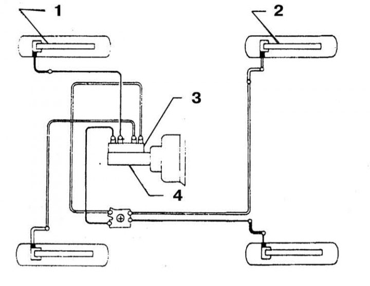
1 - Front brake mechanism; 2 - Rear brake mechanism; 3 - Non-separable pressure limiter; 4 - GTZ
Hydraulic brake circuit diagram for models equipped with LSV type ABS.
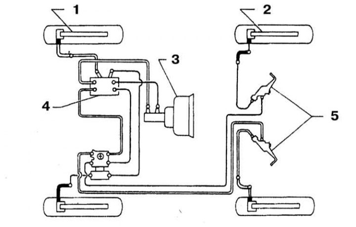
1 - Front brake mechanism; 2 - Rear brake mechanism; 3 - GTZ; 4 - ABS pressure modulator; 5 - Load Sensing Valve
Hydraulic brake circuit diagram for models equipped with DVP type ABS.
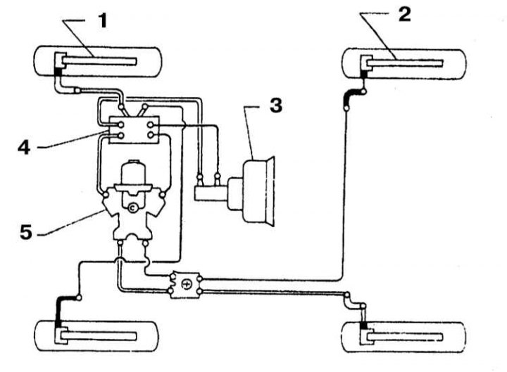
1 - Front brake mechanism; 2 - Rear brake mechanism; 3 - GTZ; 4 - ABS pressure modulator; 5 - Two-way pressure regulator
All models of cars considered in this Manual are equipped with a hydraulic brake system with vacuum booster. Disc brakes are always installed on the front wheels, while the rear wheel mechanisms can have either a disc brake or a brake system (models since 1995.), as well as drum (models produced in 1993 and 1994.) design.
All brake mechanisms are equipped with self-regulators. At the same time, wear compensation of brake pads of disc mechanisms (front and back) is carried out automatically, whereas drum brake mechanisms are equipped with special adjustment devices, which are activated when the parking brake is applied.
Hydraulic system
The dual design of the main brake cylinder (MBC) equipped with two separate reservoirs allows the hydraulic circuit to be divided into two circuits operating independently of each other. The latter means that if one of the circuits fails, the second continues to operate in the previous mode, ensuring adequate braking of the vehicle. The hydraulic circuits are arranged diagonally and failure of any of them naturally leads to a decrease in braking efficiency and is accompanied by the activation of a control lamp on the instrument panel when the foot brake pedal is depressed.
Master brake cylinder (MBC)
The brake master cylinder is mounted on the brake booster servo assembly, which is secured to the rear bulkhead of the engine compartment. On top of the cylinder is a large hydraulic fluid reservoir, equipped with a plastic cover. The reservoir is secured in the cylinder using bushings and a cylindrical pin.
As mentioned above, the master cylinder has a dual design, ensuring the operation of two independent hydraulic circuits. The fluid pressure in each circuit is pumped by an individual piston inside the master cylinder. A two-way regulator valve installed on the engine compartment bulkhead ensures the necessary balance of hydraulic forces developed in the brake mechanisms of the front and rear wheels.
Vacuum brake booster
The booster uses the vacuum created in the intake manifold to improve the efficiency of the brake system hydraulic drive. The vacuum booster servo is mounted on the rear bulkhead inside the engine compartment.
Parking brake
The parking brake cable drive is connected to the brake mechanisms of the rear wheels of the car. The brake is applied and released by means of a lever installed on the central console.
Service
After completing any maintenance procedure involving the removal or disassembly of any component of the brake system, be sure to check the efficiency of the brake system and only after making sure that it operates properly should you begin operating the vehicle. Test driving should be performed on a clean, dry and level road surface.
Check the vehicle's braking efficiency at various speeds and different foot brake pedal pressures. The vehicle should brake evenly while maintaining directional stability. Try to avoid premature wheel locking, which can result in loss of control.
Remember that factors that affect a vehicle's braking performance include tire condition and inflation pressure, vehicle load level, and proper suspension geometry.
The full article is available on the resource (NissanBook)
Precautionary measures
When servicing vehicle brake components, there are some special precautions that should be taken:
- a) Use only DOT 3 grade hydraulic fluid to fill the brake system;
- b) The friction linings of the brake pads/shoes may contain asbestos, which is harmful to health. Avoid inhaling brake dust, and do not blow it off with compressed air. Use only special cleaning agents to wipe brake components;
- c) Ensure that all required tolerances and tightening forces are observed. When servicing components, use only serviceable tools. If in doubt, seek help from specialists. Remember that proper functioning of the brakes is the key to traffic safety;
- d) At the slightest sign of malfunction of the braking system, operation of the vehicle must be suspended!