Front wheel disc brake components
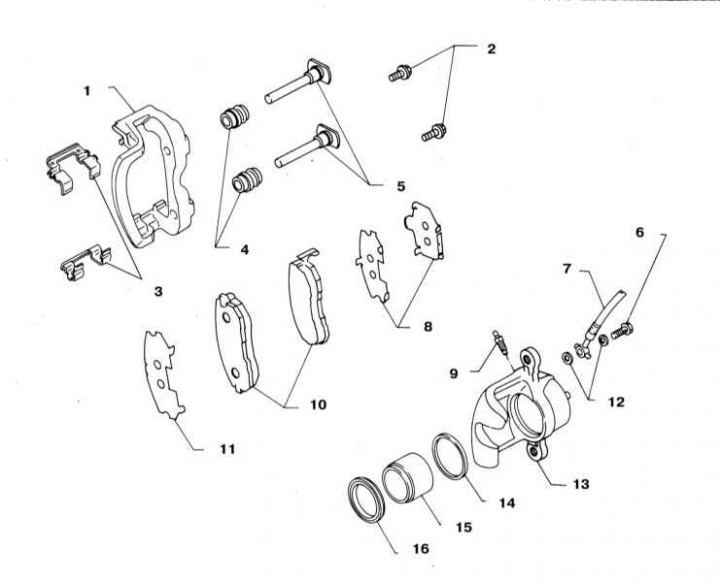
1 - Anchor bracket; 2 - Guide pin bolts (22÷31 Nm); 3 - Shoe holders; 4 - Protective covers for guide pins; 5 - Guide pins; 6 - Hollow bolt of choke connection (17÷20 Nm); 7 - Brake hose; 8 - Adjusting pads; 9 - bleed valve (7÷9 Nm); 10 - Brake pads; 11 - Adjusting pad; 12 - Copper sealing washers; 13 - The body of the working cylinder (caliper); 14 - Sealing cuff; 15 - Piston; 16 - duster
Rear wheel disc brake components
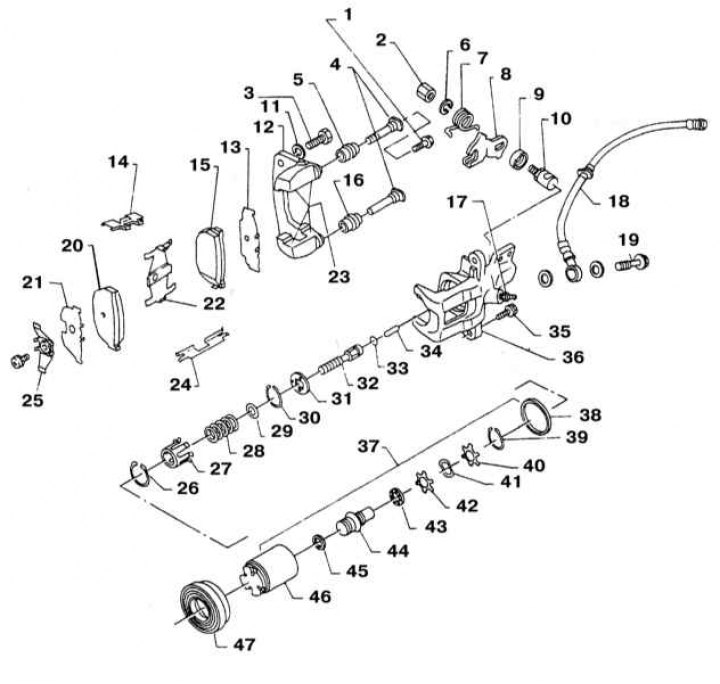
1 - Guide pin bolt (22÷31 Nm); 2 - Nut; 3 - Fixing bolt; 4 - Guide pins; 5 - Protective cover of the guide pin; 6 - Spring washer; 7 - Return spring; 8 - Executive lever of the parking brake drive; 9 - Bellow; 10 - Adjusting cam; 11 - Spring washer; 12 - Anchor bracket; 13 - Adjusting pad; 14 - The holder of pads; 15 - Inner block; 16 - Protective cover of the guide pin; 17 - bleed valve (7÷9 Nm); 18 - Brake hose; 19 - Hollow bolt of union connection (17÷20 Nm); 20 - Outer block; 21 - Adjusting pad; 22 - Retainer; 23 - Pad contact surfaces (lubricate with silicone grease); 24 - The holder of pads; 25 - Limiting spring; 26 - Retaining ring; 27 - Spring cover; 28 - Spring; 29 - Nest; 30 - Retaining ring; 31 - Overlay; 32 - Pusher; 33 - Ring; 34 - Rod; 35 - Check (22÷31 Nm); 36 - Caliper body; 37 - Piston assembly; 38 - Sealing cuff; 39 - Retaining ring; 40 - Gasket; 41 - Wavy washer; 42 - Gasket; 43 - Ball bearing; 44 - Adjusting nut; 45 - Washer; 46 - Piston; 47 - duster
Warning! Remember that the dust generated during the operation of the brake mechanisms may contain asbestos, which is extremely harmful to human health. Never blow off dust with compressed air or inhale it - wear a protective mask or respirator when servicing mechanisms. Never use gasoline or petroleum-based solvents to clean brake system components - use only branded cleaners or methyl alcohol!
Both brake calipers on the same axle must be changed at the same time.
Removing
1. The design of disc brakes is shown in the illustrations.
2. Loosen the nuts on the respective wheels. Jack up the front/rear of the vehicle and place it on jack stands. Chock the wheels on the ground. Remove wheels.
3. To disconnect the parking brake cable from the rear wheel brake actuator, unbolt the cable support bracket from the caliper assembly. Release the tip of the cable from the forked lever.
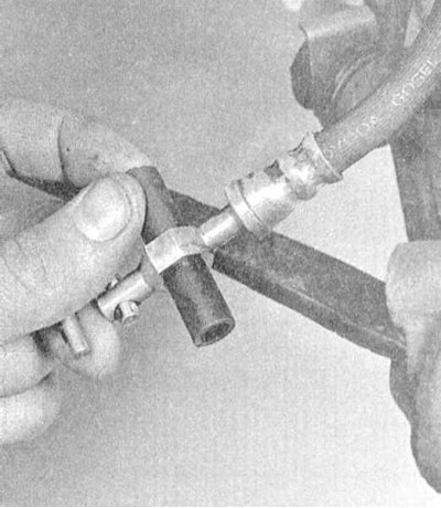
4. Turn out a hollow bolt of union connection and remove sealing washers. Disconnect the hose from the caliper. Seal the open end of the disconnected hose immediately to minimize hydraulic fluid loss.
5. Turn out fixing bolts and remove a support from a basic arm.
Installation
1. Installation is carried out in the reverse order. Don't forget to replace the copper sealing washers (gaskets) on both sides of the nipple connector for connecting to the brake hose caliper. Usually a set of new gaskets is included in the repair kit. Tighten the caliper mounting bolts and the hollow bolt of the union connection with the required force.
2. Bleed the brake circuit (see Section Bleeding the brake system). Check the brake line fittings for signs of leakage.
3. Replace the wheels, lower the vehicle to the ground and tighten the wheel nuts to the required torque (see Specifications to Chapter Settings and ongoing maintenance). Before starting the operation of the vehicle, check the correct functioning of the brakes.