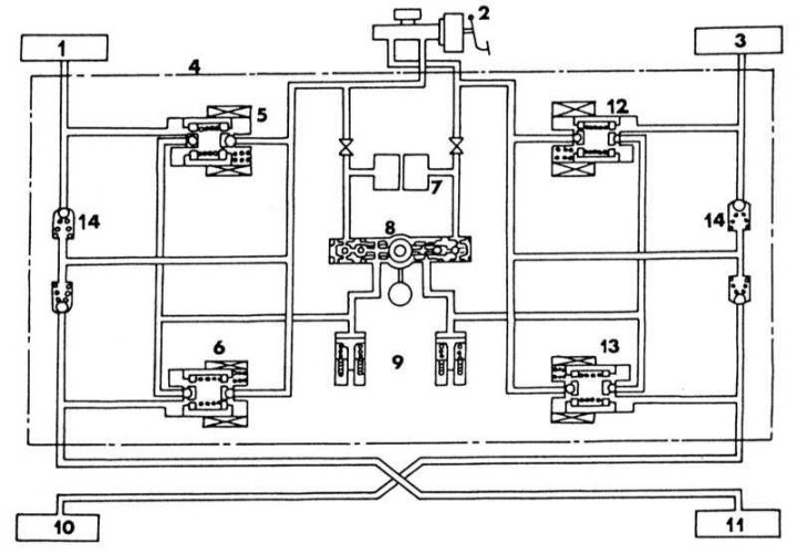
Hydraulic circuit anti-lock system (ABS)
1 - front left caliper; 2 - main brake cylinder; 3 - rear left caliper; 4 - hydraulic control device; 5 - front left control valve; 6 - rear left control valve; 7 - pulsation damper; 8 - pressure pump; 9 - expansion tank; 10 - rear left caliper; 11 - rear right caliper; 12 - front right control valve; 13 - rear right control valve; 14 - bypass valve
In general, it does not make sense to describe how the ABS system works in this manual, but you will understand your system better if you know how it works.
Usually cars with ABS have disc brakes on the rear wheels. This is also the case for Primera models, i.e. only vehicles with a 2.0l engine can be equipped with ABS as standard or as an option.
The ABS system's critical safety factor is its ability to prevent the wheels from locking up during heavy braking, so that the vehicle remains steerable. Also, during emergency braking, there is a chance to go around an obstacle. However, do not assume that the ABS system can work wonders. If the physical limits of the system are exceeded, i.e. the speed is too high, even vehicles with ABS can have an accident.
Four wheel speed sensors, which are mounted in the steering knuckles or rear hub carriers, independently monitor the number of revolutions of each wheel. In the illustrations Installation position of the front wheel speed sensor and Installation position of the rear wheel speed sensor shows where the front and rear wheel sensors are located. The microprocessor receives speed signals and detects anomalies in relation to the set parameters. Thanks to this process, the brake pressure in the corresponding wheel decreases or increases from 4 to 10 times in a matter of seconds, much faster than with the so-called impulse braking with the brake pedal, in addition, the adjustment on each wheel is carried out separately, and not on all wheels at the same time, as it is occurs when you operate the brake pedal on vehicles that do not have ABS. The rear brake circuit has two load-sensing brake pressure control valves that prevent further risk of wheel lockup, especially if the vehicle is lightly loaded.
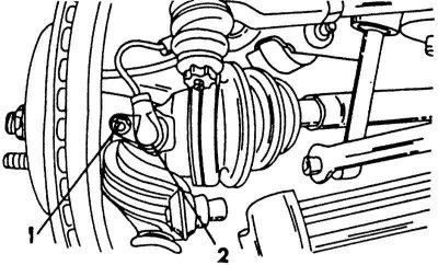
Installation position of the front wheel speed sensor
1 - bolt, 11-16 Nm; 2 - sensor
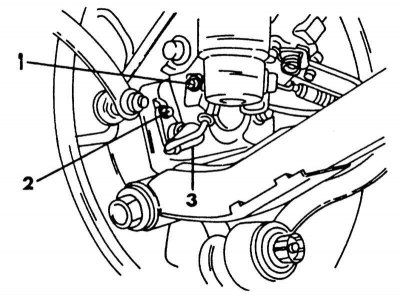
Installation position of the rear wheel speed sensor
1 - bolt, 4-6 Nm; 2 - bolt, 11-16 Nm; 3 - sensor
Two hydraulic valves precisely distribute the required brake pressure to the front wheels depending on the traction. Two other control valves control the rear brakes. In this case, the electronic control system reacts to the first wheel prone to blocking. With optimal braking, the vehicle remains steerable, directional stability is maintained and the vehicle can be kept under control. At speeds below 15 km/h, the system does not work. The illustration shows a schematic representation of the system, thanks to which you can navigate the location of the elements.
Something to be said about the hydraulic pump and pulsation damper (7) And (8). The pump supplies fluid to the pulsation damper and reduces the pressure in the calipers. The pump has an eccentric. When the pump presses the piston to the side through the eccentric, the liquid from the expansion tank is supplied to the damper, while the inlet and outlet openings and the valves connected to them open. The piston on the other side remains in its position, i.e. the intake and exhaust valves on that side remain closed. In this way, the valves control the emptying and filling of the system. The pulsation damper stores high pressure brake fluid and allows it to slowly return to the brake master cylinder.
So the ABS system provides you with additional safety.
It is not recommended to perform any work on the system yourself. The workshop will do it better. However, work is always carried out on the car that affects the ABS, such as bleeding the brakes. The following instructions must therefore be followed for all work on the brake system:
Thoroughly clean all connections and the area around them before loosening them.
Lay out the removed parts on a clean surface and cover with foil or clean paper. Do not use fluffy rags.
Cover or plug open elements of the system if repairs are not carried out immediately. This is especially true for outdoor work.
Install only perfectly clean parts. Never use parts that have been stored for a very long time.
It is very tempting to use a compressed air compressor that plugs into the cigarette lighter socket to clean parts. Never do this if the system connections are open.
After switching on the ignition, the hydraulic pump builds up working pressure in the system within 60 seconds. The ABS warning lamp lights up for 2-20 seconds, depending on the pressure in the system. The electronic control unit checks the individual components. If any malfunctions are detected, the system operates like a conventional non-ABS braking system. If this happens, i.e. the control lamp remains on, contact a workshop. In the workshop, with the help of special devices, faults can be diagnosed, which may be of an electrical or hydraulic nature.