Note. To perform this procedure, you will need a special tool - ask in car accessories stores.
1. Disconnect the negative cable from the battery.
Note. If the stereo system installed in the car is equipped with a security code, before disconnecting the battery, make sure that you have the correct combination to activate the audio system!
2. Remove the cylinder head cover (see Section Removal and installation of covers of heads of cylinders).
3. On manual transmission models, apply the parking brake and select neutral.
4. Remove the spark plugs (see chapter Settings and ongoing maintenance).
5. Bring the piston of the first cylinder to the TDC position of the end of the compression stroke, - make sure that the alignment marks are aligned correctly (see Section Bringing the piston of the first cylinder to the top dead center position (TDC)).
6. Measure the respective valve clearances. Record the measurement results and compare them with the requirements of the Specifications. Mark valves whose clearances are out of range.
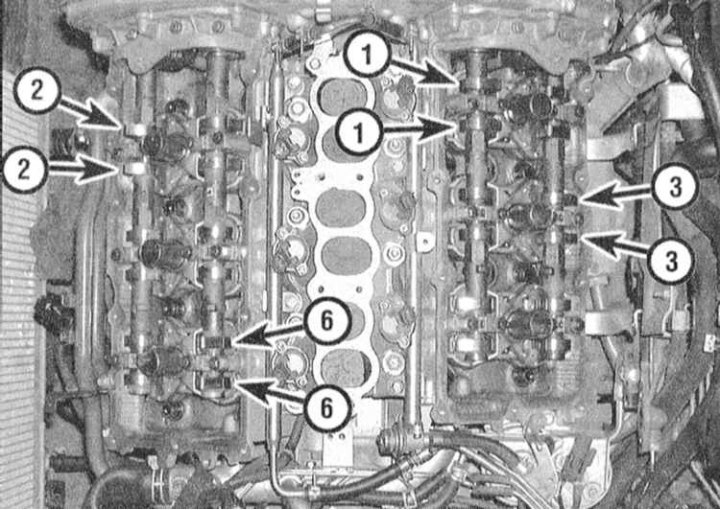
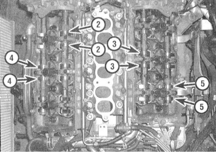
7. Turn the crankshaft in the normal direction (clockwise) 240°to bring the piston of the third cylinder to the TDC position and measure the valve clearances of the next set.
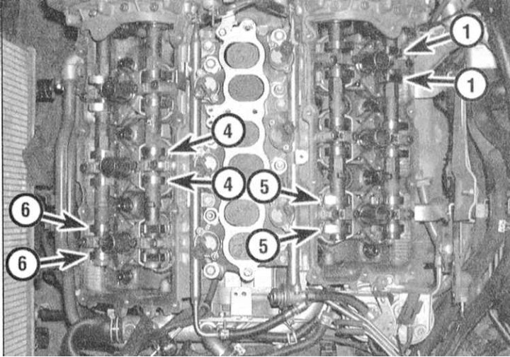
8. Rotate the shaft another 240° (TDC of the 5th cylinder) and check the clearances of the remaining valves.
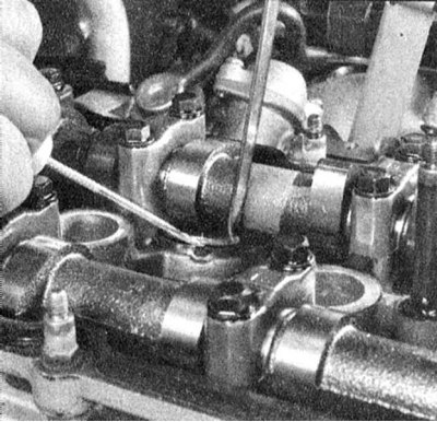
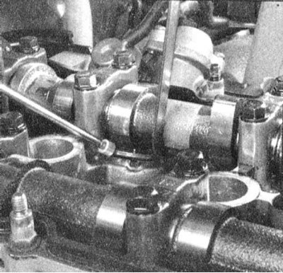
9. When you have finished measuring, turn the crankshaft pulley so that the drive cam of the first valve to be corrected turns with the working ledge up (from the pusher).
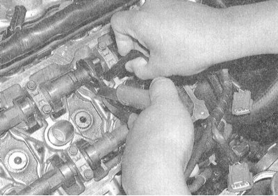
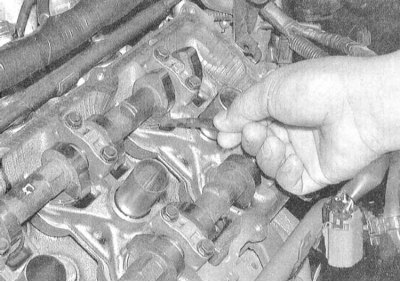
10. Expand the adjusting washer with the hole towards the central part of the cylinder head casting. Install special tongs so that their upper lips cover the shaft at the cam cheek, and the lower ones rest against the top of the washer. Squeeze the handles of the pliers and turn the tool away from the camshaft, depressing the pusher. Pass the tip of the second special tool into the gap between the edge of the pusher and the camshaft, then release the pusher. You can use tweezers to remove the shim (pry up the washers with a screwdriver) or magnetized rod.
Note. Applying compressed air to the hole in the washer will help remove it.
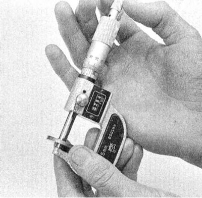
11. Measure the thickness of the removed washer using a micrometer or a vernier caliper equipped with a vernier scale (see accompanying illustration). To calculate the thickness of a new washer that must be installed on the pusher in order to adjust the valve clearance, use the following formula:
Inlet valves: N=R (M - 0.30 mm)
Exhaust valves N = R (M - 0.33 mm)
Where:
R - Thickness of the old washer in millimeters
M - Measured valve clearance in millimeters
N - New washer thickness in millimeters
12. Select a new washer such that its thickness matches the required value as closely as possible. Washers are available in 64 sizes in 0.01mm increments ranging from 2.32mm to 2.95mm.
Note. A washer removed from the tappet of one valve may be suitable as a new one to adjust the clearance of another - make the appropriate calculations before you go for new washers.
13. Acting in a manner similar to that described in paragraph 10, alternately install new matched washers on the pushers of the corresponding valves.
14. Make sure that the valve clearances are adjusted correctly (see above), if necessary, reselect washers.
15. Assembly of the head is carried out in the reverse order to the dismantling of the components.