Attention! Description applies to standard size connecting rod bearings only. Repair connecting rod bearings are not divided into size groups.
New connecting rod bearings are selected according to the size group codes printed on the crankshaft.
Codes of size groups are applied either on the cheek of the crankshaft next to the neck of the 1st cylinder (from the camshaft drive chain), or on the cheek next to the neck of the 4th cylinder (from the flywheel or torque converter drive plate). A four-digit code indicates the size groups of the connecting rod journals of the crankshaft, the first digit refers to the neck of the 1st cylinder, and the fourth to the neck of the 4th cylinder. The five-digit code refers to the size groups of the crankshaft main journals (see subsection 3.2.2.8.2).
To select the connecting rod bearing shells, you need to find out the size group of the crankshaft crankpin for a given cylinder, and then, using the attached table, determine the desired liner, guided by the color marking, which is applied in the form of a dot on the side surface of the liner.
| crankshaft code | Color marking of the dimensional group of the liner |
| 0 | black |
| 1 | brown |
| 2 | green |
Checking clearance in connecting rod bearings
1. Clean the outer surface of the connecting rod bearings and the surfaces of the bearing bores in the connecting rods and in the connecting rod caps.
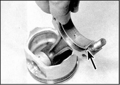
2. Push the earbuds in and place the top and bottom earbuds in place. Make sure the tabs on the bearing shells fit into the grooves in the connecting rod (indicated by arrows) and in the cap of the connecting rod.
3. When installing the earbuds, do not touch the working surface of the earbuds with your fingers. Make sure the lubrication hole in the upper connecting rod is aligned exactly with the hole in the connecting rod. If the clearance check will be performed with the old liners, then make sure that these liners are installed in their original places.
4. The clearance in the connecting rod bearings can be checked in two ways. When determining the gap in the first way, it is necessary to assemble the covers with connecting rods and connecting rod bearings, making sure that the relative orientation of these parts is correct. Tighten the nuts of the connecting rod caps to the specified torque and measure the inside diameter of each pair of bushings assembled with a bore gauge or caliper. Main bearing clearance is defined as the difference between the inner diameter of the assembled connecting rod bearings and the diameter of the corresponding connecting rod journals of the crankshaft.
5. Second way (more accurate) consists in the use of plastic Plastigage gauge wire with a round section laid on carefully cleaned surfaces of the connecting rod journals.
6. Install the connecting rod bearings with the correct orientation. Place a piece of gauge wire on each connecting rod journal of the crankshaft.
7. Clean the connecting rod bearing surfaces and install the connecting rods on the corresponding crankshaft journals. Install the connecting rod bearing caps, orienting them according to the existing marks, or the marks made during disassembly.
8. Tighten the cap nuts (see below). When tightening, changing the position of the wire is not allowed, and turning the crankshaft is also not allowed.
9. Remove the connecting rod caps without allowing the crankshaft to rotate or the gauge wire to move. Compare the flattened wire width to the scale on the package and determine the clearance in the main bearings.
10. If the clearance differs from the standard, then the reason may be the wrong selection of connecting rod bearings (or their increased wear if used liners were checked). Before concluding that the bearings need to be replaced, make sure that there is no dirt or oil between the surfaces of the caps or connecting rods and the bearing when measured. If the width of the flattened wire from one edge is greater, then this indicates a tapered crankpin.
11. If the clearance differs from the norm when measuring with old liners, then repeat the measurements with new liners. If, even with new liners, the gap exceeds the norm, then you should seek advice from the dealer's car service, or a specialist in this engine, in order to get advice on how to proceed. It is possible that you will have to regrind the crankshaft crankpins and replace the liners with repair ones.
12. If necessary, purchase liners of the appropriate size group and repeat the procedure for measuring the clearance in the connecting rod bearings.
13. When finished, scrape off the remnants of the calibration wire from the main journals of the crankshaft with a fingernail or a wooden chip, without damaging their surface.
Installing the connecting rod and piston group
The following description is based on the assumption that the assembly will be carried out after the crankshaft assembly with all main bearings and covers has been installed (with lid frame).
1. Make sure the connecting rod bearings are installed correctly (see paragraphs. 4 and 5). If new bearings are to be installed, carefully remove the remaining preservative grease by washing them in kerosene. Dry the connecting rods and bearings with a lint-free cloth.
2. Make sure that the joints of the piston rings are correctly aligned and compress the rings with a special tool.
3. Lubricate the cylinders, pistons and rings, then lay out the pistons and connecting rods in the order in which these parts will be installed on the engine.
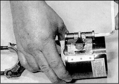
Start the assembly from the 1st cylinder. Make sure the piston rings are properly aligned (see subsection 3.2.2.12) and squeeze the rings with a special tool.
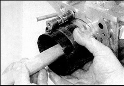
5. Insert the piston and connecting rod assembly into the first cylinder. Orient the piston so that the mark on the piston crown (in the form of an arrow or a dash) facing towards the camshaft chain cover. Tap the piston lightly with a hammer handle or a wooden block so that the piston enters the cylinder and the piston bottom is level with the split plane of the cylinder block.
6. Make sure the connecting rod bearings are installed correctly and generously lubricate the bearing shells and the crankshaft journal. Being careful not to damage the cylinder surface, tighten the connecting rod to the crankshaft journal. Put on the connecting rod cap with insert and tighten the nuts by hand. Keep in mind that the planes on the connecting rod and on the connecting rod cap, which are labeled, must be aligned (this means that the locating lugs of the connecting rod bearings are opposite each other).
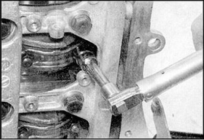 | 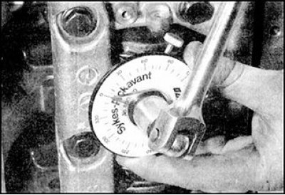 |
7. Tighten the nuts of the connecting rod caps to the torque of the 1st tightening stage using a torque wrench and socket (photo on the left). Then tighten the nuts to the angle of the 2nd stage of tightening, or if a wrench with an angle scale is not available, tighten to the torque of the 2nd stage (photo on the right).
8. Turn the crankshaft and check the freedom of its rotation. If new parts are installed, then there should be a noticeable constant resistance to the rotation of the crankshaft, however, the crankshaft should turn smoothly, without jamming.
9. Install the rest of the pistons and connecting rods in the same way.
10. Install cylinder head, chain (or chains) camshaft drive and oil pan.