2. Wipe the back surface of the new upper connecting rod bearing and lay it in place in the connecting rod. Make sure the tab on the bushing is in the groove in the connecting rod and the lubrication holes line up (photo). Do not lubricate the insert. Install the bottom bearing into the connecting rod cap in the same manner.
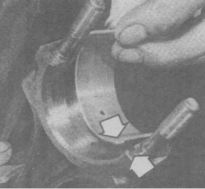
22.2 Inserting the bearing into the connecting rod
3. Arrange the joints of the piston rings in accordance with the diagram (photo).
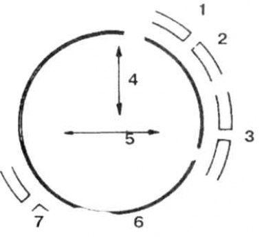
22.3a Arrangement of joints of piston rings (until 1990)
1. Top compression ring; 2. The upper disk of the oil scraper ring; 3. Oil scraper ring expander; 4. The plane of rotation of the crankshaft; 5. Finger axis; 6. Lower oil scraper disc
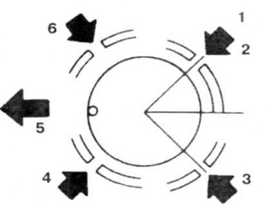
22.3b Arrangement of joints of piston rings (after 1990)
1. Top compression ring; 2. The upper disk of the oil scraper ring; 3. The lower disk of the oil scraper ring; 4. Lower compression ring; 5. To the front of the engine
4. Lubricate the pistons and rings with clean engine oil, compress the rings with a tool (photo), leaving a protruding section of the piston.
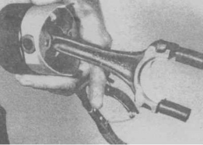
22.4 Preparing the piston and connecting rod for installation in the cylinder is no different from the procedure for main bearings (see above). Rotation of the crankshaft or the slightest ingress of oil on the liners during measurements is not allowed. Tighten the connecting rod cap nuts to the specified
5. Turn the crankshaft to bottom dead center in the first cylinder, lubricate the cylinder walls with engine oil.
6. Orient the piston so that the F mark or punch (on V6 engine) facing towards the front of the engine (photo).
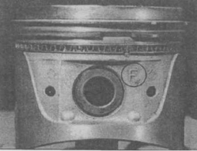
22.6a Mark F on the piston of a 4-cylinder engine
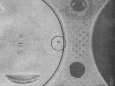
22.6b Punching on the piston of the V6 engine
7. Carefully insert the lower part of the piston with the connecting rod into the first cylinder until the ring presser stops against the cylinder block. Lightly tap the top edge of the mandrel to evenly contact the plane of the cylinder block.
8. Insert the piston into the cylinder by gently tapping the piston head with a wooden handle of a hammer (photo). Don't put in a lot of effort.
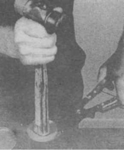
22.8 Introduction of the piston into the cylinder
9. Pull the connecting rod to the crankshaft journal and check the clearance in the connecting rod bearing (photo).
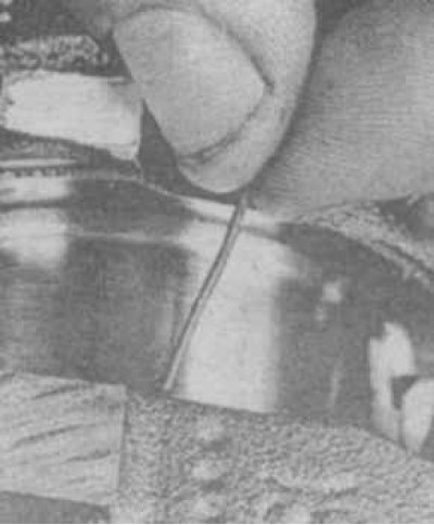
22.9a Section of the gauge for measuring the clearance in the connecting rod bearing
22.9b Clearance determination
Verification procedure
10. Carefully remove the remnants of the caliber, lubricate the liners and the crankshaft journal, install the cover and evenly tighten the nuts to the specified torque.
11. Repeat these operations for other rods.
12. After the final installation of pistons with connecting rods, check the freedom of rotation of the crankshaft.
13. Check the end play of the connecting rod (see above). Keep in mind that after installing new parts, the play and may be less than normal and grinding of the connecting rods will be required.
14. Collect and establish the engine, being guided by corresponding sections.