It is understood that the gap between the ring and the seat of the groove has already been checked and is correct.
2. Lay out the pistons with connecting rods and new piston rings in such order that the set of rings matches the cylinder on which the clearance will be measured.
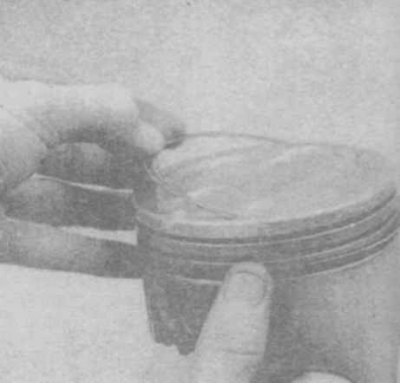
3. Insert the upper ring into the first cylinder and push the piston head inward, so that the ring inside the cylinder becomes perpendicular to its axis (photo). The ring should be at the bottom of the cylinder, in the position corresponding to the bottom dead center.
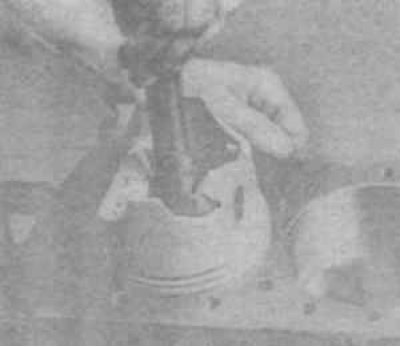
19.3 Fitting the piston ring to measure the joint gap
4. Measure the gap with feeler gauges and compare the result with the standard value (photo). If the clearance is greater or less than the specified value, then once again check the correct selection of the rings.
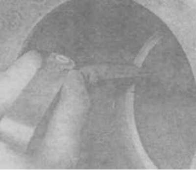
19.4 Measuring the piston ring gap
5. If the gap is too small, then file the ends (photo).
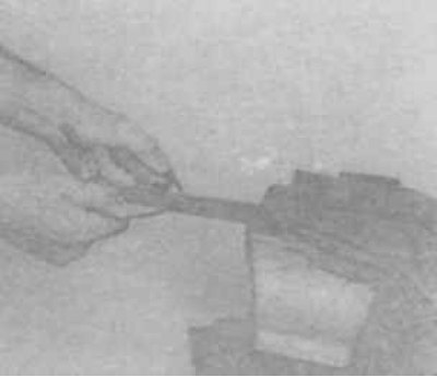
19.5 Sawing the ends of the ring
6. A gap in the joint of the ring is allowed up to 1 mm.
7. Check the gap in each ring.
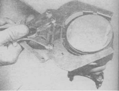
8. Install the rings on the piston, starting with the oil scraper. Install spacer/expander in groove (photo). Make sure you have a pin (if provided) and install the lower and upper disks. When installing oil scraper discs, it is impossible to use a device for dressing rings, as they may break.
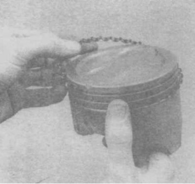
19. 8a Installing the scraper ring expander
19.8b Installing the oil scraper disc
9. After installing all parts of the oil scraper ring, make sure that the upper and lower discs rotate freely in the groove.
10. Install the middle and top rings. The mark on the middle ring must face the piston crown (photo).
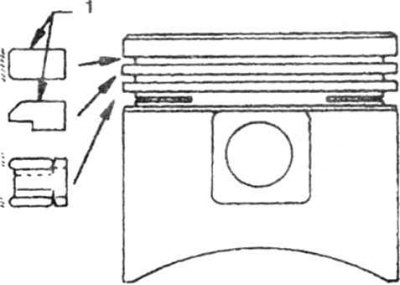
19.10a Cross profiles of rings
1. Marking
19.10b Installation of piston rings using an expander
Attention! Always follow the instructions on the piston ring packaging - different manufacturers may have different indications for the correct orientation of the ring. Do not confuse the top and bottom compression rings as they have different cross profiles.