Removal - GA engine
1. Remove the mudguard (And) engine.
2. Drain the engine oil.
3. Remove the exhaust pipe (see chapter «exhaust system»).
4. Remove the center beam.
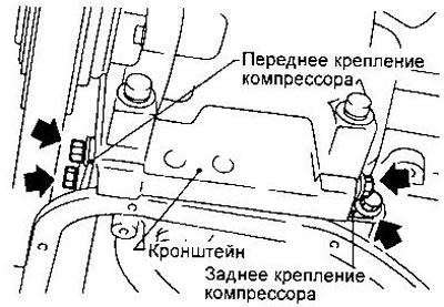
5. Remove the front and rear engine support brackets.
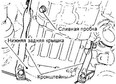
6. Remove the bottom rear engine cover (models with automatic transmission).
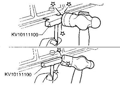
7. Insert a sealant cutter between the cylinder block and the oil pan.
Be careful not to damage the aluminum surfaces. Do not separate the pallet with a screwdriver. This will deform the sump flange.
Cut through the sealant around the perimeter, advancing the cutter with hammer blows, and remove the oil pan.
Installation - GA Engine
1. Before installing the oil pan, remove all traces of old sealant from the sealing surfaces of the pan and cylinder block.
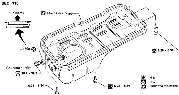
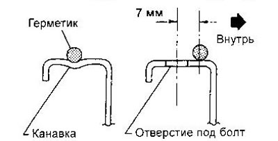
2. Apply a continuous bead of sealant to the oil pan flange. Use genuine Genuine Liquid Gasket or equivalent. The thickness of the roller should be 3.5-4.5 mm. The installation of the pan must be done within 5 minutes after applying the sealant.
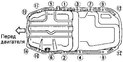
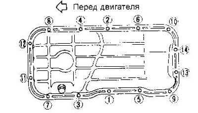
3. Install the oil pan and tighten the bolts in the sequence shown in the figure. Oil can be poured no earlier than 30 minutes.
4. Establish other details in sequence, return to removal.
Removal - SR Engine
1. Remove the engine mudguard.
2. Drain the engine oil.
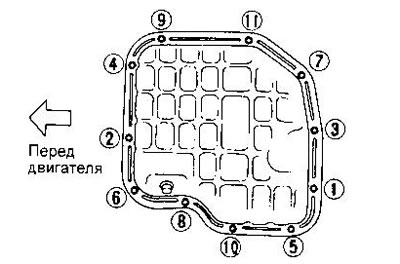
3. Turn away bolts of fastening of the steel pallet in the sequence specified in drawing.
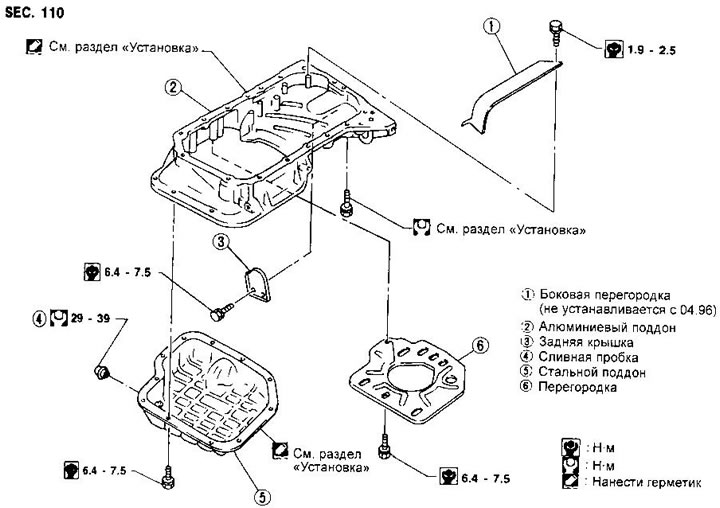
4. Separate the steel pan as described for GA motors (observe the indicated precautions).
5. Remove the steel pallet baffle.
6. Remove the oil receiver tube.
7. Place a jack under the gearbox and raise the engine.
8. Remove the center beam.
9. In models with an automatic transmission disconnect a cable of management from a transmission.
10. Remove compressor support brackets.
11. Remove the back cover.
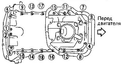
12. Turn away bolts of fastening of the aluminum pallet in the sequence specified in drawing.
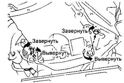
13. Turn away two bolts of fastening of a transmission and screw them in the apertures shown in drawing. Tighten the bolts until the aluminum pan separates from the cylinder block.
14. Remove the aluminum pan as described for GA engines (observe the indicated precautions).
15. Turn out the bolts used for separation of the pallet.
Installation - SR Engine
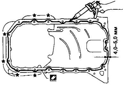
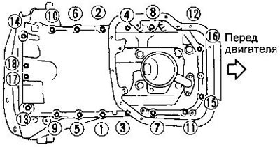
1. Install the aluminum tray. The installation procedure is the same as for GA motors, except that the bead of sealant must be 4.0-5.0 mm thick and wrap around the outside of the bolt holes marked with an asterisk in the illustration.
The tightening sequence for the aluminum pallet bolts is shown in the figure. Tightening torques:
- Bolts 1-16 - 16-19 Nm
- Bolts 17, 18 - 6.4-7.5 Nm
2. Wrap two bolts of fastening of a transmission. The tightening torques are given in the respective chapter.
3. Install the back cover.
4. Install the compressor brackets.
5. Connect the control cable to the automatic transmission.
6. Install the center beam.
7. Install the oil receiver tube.
8. Install the steel pallet baffle.
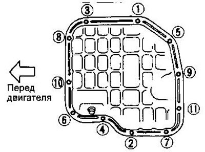
9. Install the steel pan in the same way as the aluminum pan. The thickness of the sealant bead is 4.0-5.0 mm, all bolt holes must be turned around from the inside.
Tighten the bolts of the steel pallet in the sequence shown in the figure. Oil can be filled no earlier than 30 minutes after installation.
Removal and installation - CD engines
Removal and installation of the oil pan is basically the same as for GA engines. When installing, apply sealant to the front and rear gaskets at the locations shown in the illustration.

The bolts are tightened in the sequence shown in the figure.
- Tightening torque - 7-8 Nm