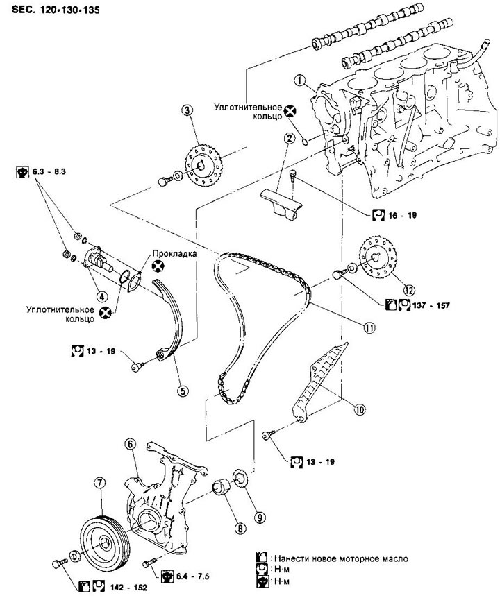
1. Cylinder block
2. Chain guide
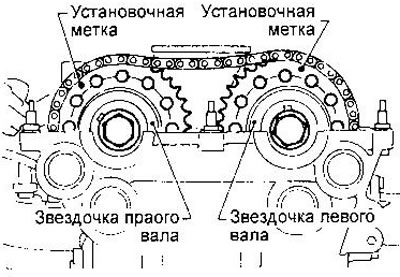
3. Right camshaft drive sprocket
4. Drive chain tensioner
5. Tensioner shoe
6. Front crankcase
7. Crankshaft pulley
8. Oil pump drive spacer
9. Crankshaft sprocket
10. Chain guide
11. Drive chain
12. Left camshaft drive sprocket
Removing
WARNING: After removing the drive chain, do not turn the crankshaft and camshaft separately to avoid damaging the pistons and valves.
1. Relieve the pressure in the supply system (see chapter «fuel injection system»).
2. Remove the lower engine splash guards.
3. Remove the right wheel and engine side mudguard.
4. Drain the coolant from the radiator and cylinder block.
5. Remove the radiator.
6. Disconnect the air line from the intake manifold.
7. Remove drive belts and water pump pulley.
8. Remove the generator and power steering pump.
9. Disconnect vacuum hoses, fuel lines, wires, etc.
10. Remove all spark plugs.
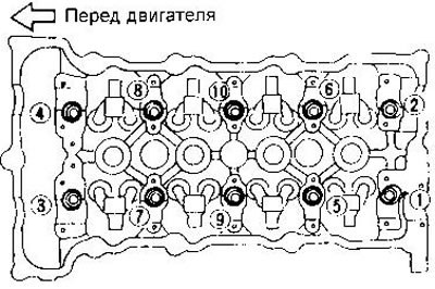
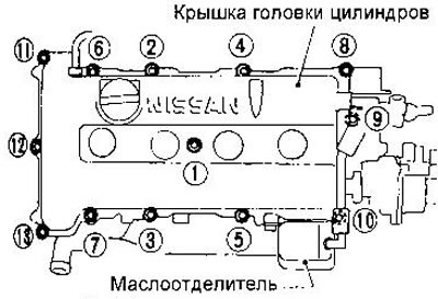
11. Remove the cylinder head cover and oil separator. The bolt loosening sequence is shown in the figure.

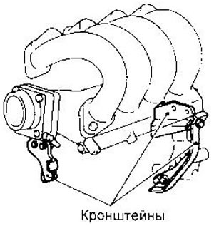
12. Remove the intake manifold brackets.
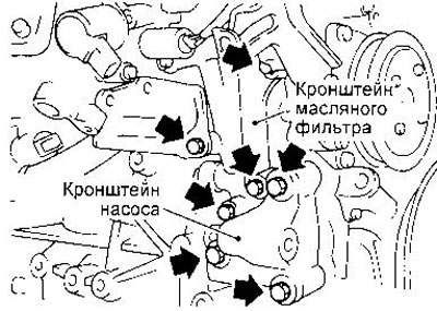
13. Remove the oil filter and power steering pump brackets.
14. Set the piston of the 1st cylinder to the TDC of the compression stroke.
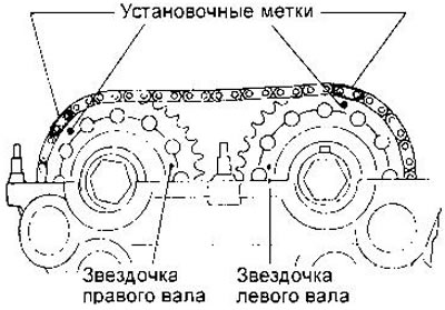
The alignment marks on the camshaft sprockets should be located as shown in the figure.
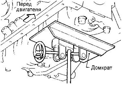
15. Remove the chain tensioner.
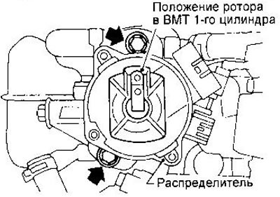
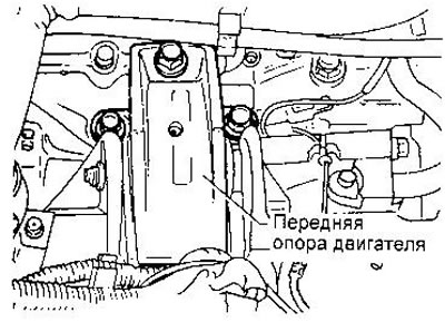
16. Remove the ignition distributor. Do not turn the rotor with the distributor removed.
17. Remove the chain guide.
18. Remove the drive sprockets of the camshafts, keeping the shafts from turning (on the necks of the shafts near the sprockets there are special hexagons).
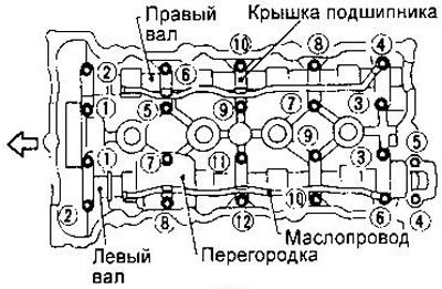
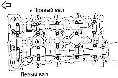
19. Remove the camshaft bearing caps, shafts, oil lines and baffle. Loosen the cover bolts in the sequence shown in the figure.
20. Remove the starter.
21. Disconnect water hoses from the block of cylinders and a radiator.
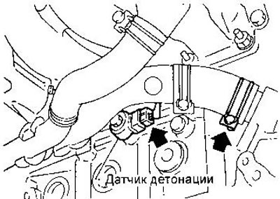
22. Disconnect the knock sensor connector.
23. Turn away external bolts of a head of cylinders.
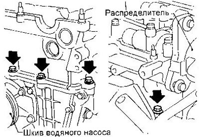
24. Turn away bolts of fastening of a head of cylinders. Loosen the bolts in two or three steps, in the sequence shown in the figure.
25. Remove the cylinder head along with the intake and exhaust manifolds.
26.Remove the oil pan (see relevant section of this chapter).
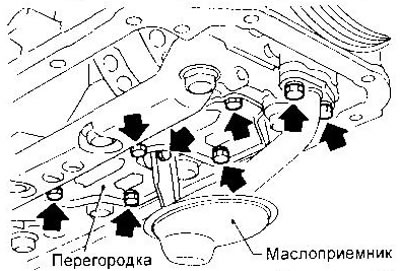
27. Remove the oil receiver.
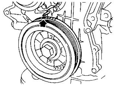
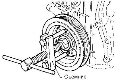
28. Remove the crankshaft pulley.
29. Install a transmission jack under the crankshaft main bearings.
30. Remove the front engine mount.
31. Remove the front crankcase and oil pump drive spacer.
32. Remove the tensioner shoe and chain guide, and then the chain itself.
Installation
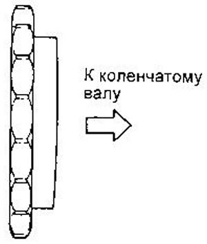
1. Install the crankshaft sprocket. The marks on the sprocket should point away from the engine.
2. Set the crankshaft to a position where the piston of the 1st cylinder is at TDC on the compression stroke. The pin should be on top. Slide the drive chain onto the crankshaft sprocket, aligning the timing marks.
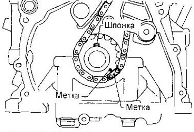
The alignment marks on the chain have the following colors:
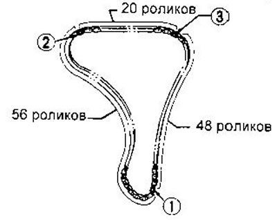
1 - golden; 2, 3 - silver.
3. Install the tensioner shoe and damper.
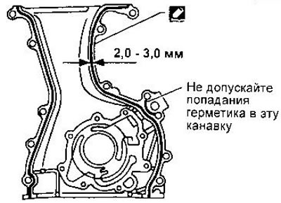
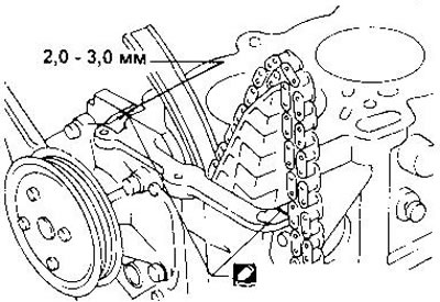
4. Before installing the front crankcase, remove all traces of old sealant from the mounting surfaces of the crankcase and cylinder block.
Apply a continuous bead of sealant to the front crankcase as shown. Make sure the new crankshaft front oil seal is installed in the correct direction.
5. Install the oil pump drive spacer and front crankcase.
6. Remove the sealant squeezed out from the joints of the front crankcase with the cylinder block at the top and bottom.
7. Install the front engine mount.
8. Install the crankshaft pulley.
9. Set the piston of the first cylinder to the TDC of the compression stroke according to the marks on the pulley (see subsection «Withdrawal»).
10. Install the oil receiver and oil pan.
11. Before installing the cylinder head gasket, apply sealant to the locations shown in the figure.
12. Install the cylinder head along with the intake and exhaust manifolds.
Apply engine oil to the cylinder head bolt threads and seating surfaces before installing.
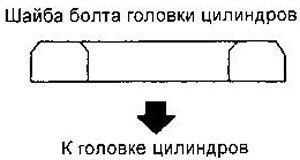
Make sure there are washers between the bolts and the cylinder head.
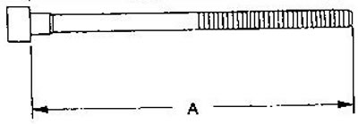
WARNING: Cylinder head bolts can be reused if length A does not exceed 158.2 mm.
Tightening sequence:
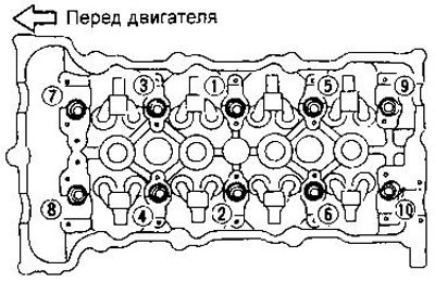
a) Tighten all bolts in the sequence shown in the figure to 39 Nm.
b) Tighten all bolts to 78 Nm.
c) Loosen all bolts completely.
d) Tighten all bolts to 34-44 Nm.
e) Tighten all bolts by 90-95°. If a protractor wrench is not available, mark the sides of the bolts facing the front of the engine, then tighten the bolts to approximately the correct angle.
f) Tighten all bolts another 90-95°. When using the second tightening method, the marks on the bolts should be directed towards the rear of the engine. Turning angles of 90°are preferred, 95°is the maximum allowable deviation.
Do not tighten the bolts immediately by 180-190°.
13. Wrap external bolts of a head of cylinders.
14. Attach the removed water hoses and knock sensor connector.
15. Install the starter.
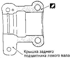
16. Apply sealant to the cover of the rear bearing of the left camshaft, having previously removed traces of the old sealant from the cover and cylinder head.
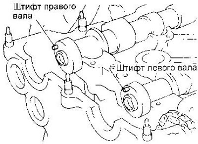
17. Install the camshafts, arranging them as shown in the figure: the pin of the left shaft should be located on top, the pin of the right shaft should be approximately at an angle of 60°to the vertical.
Before installing the shafts, lubricate their necks and cams with engine oil.
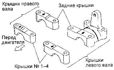
18. Install the bearing caps, positioning them as shown.
Apply engine oil to the threads and seating surfaces of the bolts before installing the covers.
Bolt tightening sequence:
- a) For the right shaft, tighten bolts 9-10, then bolts 1-8 with a torque of 2 Nm in the sequence shown in the figure. For the left shaft tighten bolts 11-12. then bolts 1-10 with a torque of 2 Nm in the sequence shown in the figure.
- b) Tighten the bolts in the same sequence to 6 Nm.
- With) Tighten bolts A-B, DF to 9.8-11.8 Nm bolt C to 18-25 Nm in the above sequence.
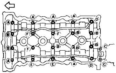
For SR20DE engines installed on European models from 04.96, tighten bolts A and B to 9.8-11.8 Nm, bolt C to 18-25 Nm in the above sequence.
19. Install the camshaft drive sprockets by aligning the marks on the chain with the marks on the sprockets.
Before tightening the bolts, apply engine oil to their threads and seating surfaces.
Tighten the bolts to a torque of 137-157 Nm. When tightening, hold the camshafts by the hexes next to the front journals.
20. Install the drive chain guide.
21. Install the ignition distributor. The camshaft must be in the position shown in the figure.
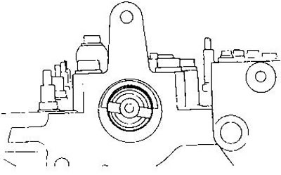
Make sure that the piston of the 1st cylinder is set to TDC and the position of the distributor rotor corresponds to the ignition moment in the 1st cylinder.
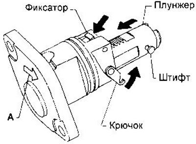
22. Install the chain tensioner. To do this, press the latch and push the plunger so. so that you can put the hook on the pin. After the tensioner is installed, the plunger will be automatically released. Arrow A must point to the front of the engine.
23. Install the brackets for the oil filter, power steering pump and intake manifold.
24. Apply sealant to the cylinder head cover gasket and cylinder head at the locations shown in the figure. Before doing this, carefully remove the remnants of the old sealant.
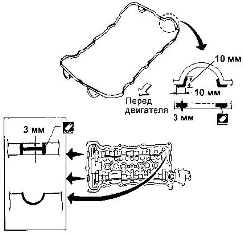
25. Install the cylinder head cover and oil separator.
Tightening sequence:
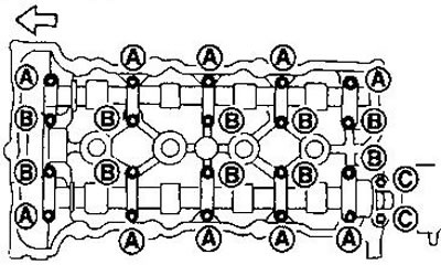
- A) Tighten nuts 1-10-11-13-8 in this order to 4 Nm. For SR20DE engines installed in European models from 04.96, the tightening torque is 8-10 Nm.
- b) Tighten nuts 1-13 to 8-10 Nm in the sequence shown in the figure.
26. Screw in the spark plugs.
27. Attach all vacuum hoses, fuel lines and wires.
28. Install the power steering pump and generator.
29. Install water pump pulley and drive belts.
30. Connect the air line to the intake manifold.
31. Install the radiator, connect the water hoses and fill the liquid into the cooling system (see chapter «Maintenance»).
32. Install engine mudguards and right wheel.