Attention! Valve clearances are checked only on a hot engine. The manufacturer has set standard clearances for a warm and cold engine. Clearances on a cold engine are checked only before starting the engine after a major overhaul. After warming up the engine, check the clearances again.
Checking and adjusting the clearances are performed only after a significant vehicle mileage, engine overhaul, or when looking for reasons for a drop in engine power, if there is a suspicion of a malfunction of the valve drive mechanism.
1. The clearances should only be checked in case of increased noise from the valve drive side, after an overhaul of the engine, or in case of looking for reasons for a drop in engine power, if there is a suspicion of a malfunction of the gas distribution mechanism.
2. Draw the outline of the engine on a piece of paper and indicate the location of cylinders 1 to 4, given that the 1st cylinder is located on the side of the camshaft drive chain cover. Indicate the position of each of the valves, as well as write down the gap that must be observed in accordance with the technical data. At the image of the valve in the diagram, draw two lines, which will indicate the measured gap and the amount by which the gap needs to be adjusted.
Attention! The manufacturer sets two groups of valve clearance tolerances. One group is for checking clearances, and the other is for adjusting and setting valve clearances. The check group tolerances are the largest, however it is highly recommended to keep all clearances within the tolerance adjustment group (although this condition is not strictly necessary).
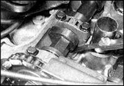
3. Warm up the engine, switch off the ignition and remove the cylinder head cover.
4. Set the piston of the 1st cylinder to the TDC of the compression stroke.
5. Use a feeler gauge to measure the clearance between the camshaft cam and the lifter on the following valves, recording each result:
- 1st cylinder - intake and exhaust valves;
- 2nd cylinder - inlet valves;
- 3rd cylinder - exhaust valves.
6. Rotate the crankshaft 360°clockwise, aligning the TDC mark with the pointer. In this position of the crankshaft, the piston of the 4th cylinder is at TDC of the compression stroke.
7. Measure the clearance in the following valves, recording each result:
- 2nd cylinder - exhaust valves;
- 3rd cylinder - inlet valves;
- 4th cylinder - intake and exhaust valves.
8. Calculate and record the difference between the measured and standard clearances. If the gap in any valve differs from the standard, then replace the adjusting washer of this valve, choosing a new washer in thickness.
9. To get the adjusting washer, it is necessary to press the pusher a sufficient distance, overcoming the force of the valve spring. To do this, the camshaft must be turned so that the cam of the corresponding valve is facing away from the pusher. Then turn the tappet so that the groove on it is at right angles to the camshaft axis.
10. Using an open end wrench or a sturdy screwdriver against the camshaft, and acting as a lever, depress the pushrod far enough to allow the gasket to slide out. After removing the gasket, slowly release the pusher. If the gasket cannot be removed, then the camshaft will have to be removed (see subsection 3.1.1.10).
11. The thickness of the shim is indicated on its underside (for example 224 means thickness 2.24mm), however, it is recommended to measure the washer with a micrometer, as the thickness may decrease due to wear.
Attention! Spare parts are supplied with washers with a thickness of 2.00 to 2.98 mm in increments of 0.02 mm.
12. If the measured gap is less than the standard, then subtract the measured gap from the standard, then subtract the result from the thickness of the removed washer.
Example:
- Inlet valve clearance too low
- Measured gap 0.26mm
- Standard clearance 0.36 mm (0.32 to 0.40 mm)
- Difference 0.10 mm
- Installed washer thickness 2.50 mm
Required thickness 2.50 - 0.10 = 2.40 mm 13. If the measured gap exceeds the standard, then subtract the standard from the measured gap, then add the result to the thickness of the removed washer.
Example:
- Exhaust valve clearance is too high
- Measured clearance 0.51 mm
- Standard clearance 0.41 mm (0.37 to 0.45 mm)
- Difference 0.10 mm
- Installed washer thickness 2.76 mm
- Required thickness 2.76 + 0.10 = 2.86 mm
14. Press the pushrod out, then reinstall the correct thickness shim with the marked side facing down. Make sure the washer is installed correctly, then repeat the procedure for other valves that are not within specification (If there are any).
15. After adjusting the clearances, turn the crankshaft at least 4 turns in the direction of normal rotation. Check the valve clearances again.
16. If all the clearances are correct, then install the cylinder head cover, install the remaining removed parts.