Attention! The camshaft drive mechanism in early production engines is distinguished by the presence of a horizontal guide bar and upper chain damper, which are absent in late production engines.
Removing
1. Set the piston of the 1st cylinder to the TDC of the compression stroke.
2. Remove the cylinder head cover.
3. Remove front cover (see subsection 3.1.1.6).
4. On cars of early releases turn away bolts and remove the directing level of the top chain.
5. Hook the tensioner shoe and move it away from the upper chain, fix the shoe in this position. Loosen the two bolts and remove the tensioner shoe.
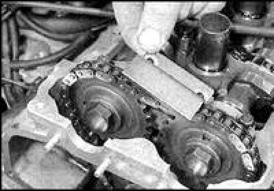
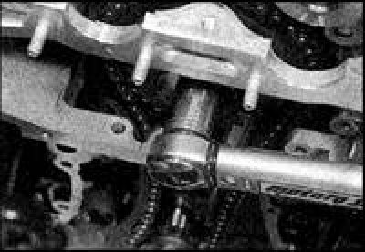
6. On later engines, move the tensioner shoe away from the upper chain and secure by laying a bar. Loosen the two bolts and remove the shoe.
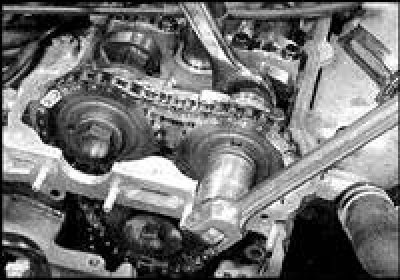
7. Holding the camshaft by the flats at the front with a wrench, remove the camshaft sprocket bolts.
8. Get bolts together with washers.
9. Disengage both camshaft sprockets from the chain and manipulate to remove the sprockets.
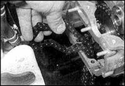
10. Disengage the upper chain from the intermediate sprocket and manipulate it out of the cylinder head.
11. Loosen the lower chain tensioner axle bolt and remove the shoe.
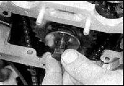
12. Turn away a bolt of an intermediate asterisk, remove a bolt together with a washer, get an asterisk and the roller.
13. Remove the lower chain from the crankshaft drive sprocket and remove from the engine.
14. Remove the drive sprocket and key from the crankshaft toe (if weakened), store the key with the sprocket.
Attention! When removing the camshaft drive chains, the rotation of the crankshaft is not allowed.
Examination
1. Check the drive, driven and intermediate sprocket for signs of wear and defects such as chipping, hooking or missing teeth. If any of these signs of wear and damage are found, all sprockets and both chains should be replaced. Chains and sprockets change as a set.
2. Inspect the chain links, check the wear of the rollers. The degree of chain wear can be determined by the deflection in the horizontal plane. There is almost no deflection in the new chain. If there is noticeable lateral play in the chain links, both chains should be replaced.
3. Keep in mind that the chain should also be replaced regardless of the presence of external signs of wear after a significant mileage, or if noticeable noise is heard from the chains while the engine is running. It is strongly recommended to change the chain complete with sprockets. Otherwise, if a new chain is installed on worn sprockets, the wear of the new chain will increase. If the condition of the chains and sprockets is in doubt, then seek qualified advice from a Nissan car service.
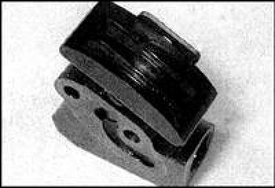
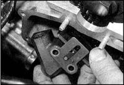
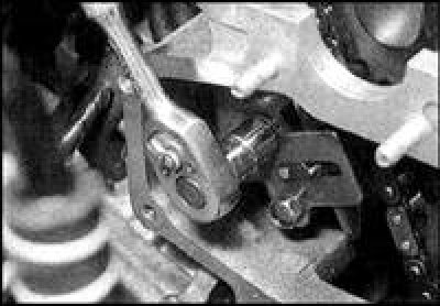
4. Check the chain tensioners and guides for signs of wear or damage. If defects are found, replace these parts (in the photo - chain tensioner with signs of wear).
5. Check the upper chain tensioner shoe shoe, make sure the tensioner plunger moves freely inside the shoe. Check the condition of the tensioner spring by comparing it with a new one. If damage or wear is found in the shoe pad, or if the condition of the spring is questionable, the tensioner should be replaced.
Installation
Upper chain, decal links and alignment marks
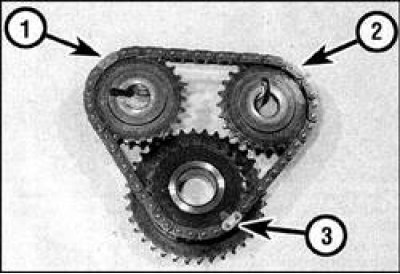
1. Intake camshaft sprocket mark and corresponding chain link
2. Mark on exhaust camshaft sprocket and corresponding chain link
3. Label on intermediate sprocket and corresponding chain link
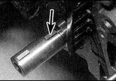
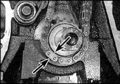
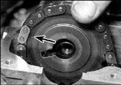
1. Make sure the 1st cylinder is at TDC on the compression stroke (The keyway on the crankshaft toe must point vertically upwards as viewed from the right side of the engine). Insert the key into the groove on the crankshaft toe (in the direction of the arrow).
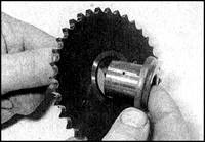
2. Orient the drive sprocket so that the alignment mark is directed away from the crankshaft, align the groove in the sprocket with the key, and put the sprocket on the toe of the crankshaft.
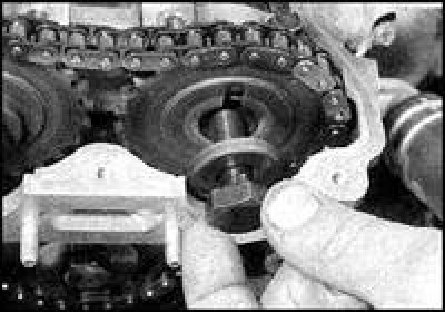
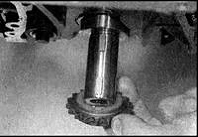
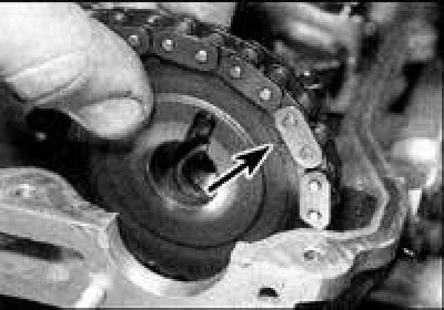
3. Lightly coat the intermediate sprocket shaft with fresh engine oil and slide the sprocket onto the shaft with the shaft flange facing the cylinder block. Engage the intermediate sprocket with the lower chain, aligning the outer timing mark with one of the silver colored chain links.
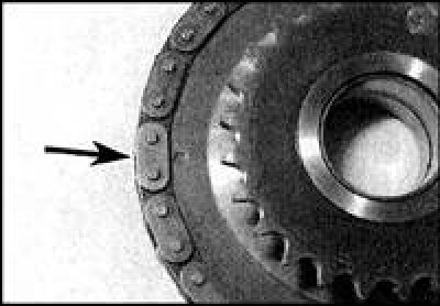
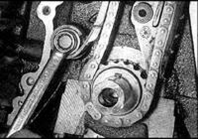
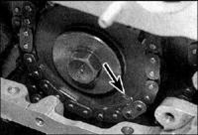
4. Install the chain with the intermediate sprocket in place so that the second link with the distinctive color matches the alignment mark on the crankshaft drive sprocket. The alignment mark looks like a small groove on the hub of the drive sprocket (arrow).
5. Make sure the labels (indicated by arrows) on the intermediate and drive sprockets are aligned with the silver chain links.
6. Wrap the bolt with the intermediate sprocket washer and tighten to the specified torque.
7. There are three distinctively colored links on the upper drive chain, each of which matches the alignment mark on each of the sprockets covered by the chain. Links with a different color are located at different intervals. On engines of early releases, all three links are silver in color. First painted link (which must match the mark on the intake camshaft sprocket) separated from the second colored link (which matches the mark on the exhaust camshaft sprocket) 16 rollers, and the third painted link is 22 rollers apart from the first (see fig. Upper chain, decal links and alignment marks).
8. On late production engines, the intervals between the painted links of the upper chain are the same, and the link corresponding to the timing mark of the intermediate sprocket is golden (the rest of the links are silver in color and must be aligned with the marks of the driven camshaft sprockets).
9. Referring to step 7, reinstall the top chain with the painted links facing out. Put the chain on the intermediate sprocket, aligning the appropriate link with the mark (arrow) on an asterisk.
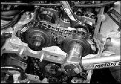
10. Install the camshaft sprockets with the alignment marks facing out (both driven sprockets are the same). Fit the chain so that the silver colored links line up with the timing marks. Make sure that all color-coded top chain links are exactly centered with the corresponding marks on the sprockets (arrow).
11. Orient the sprockets on the camshafts by aligning the slots with the dowel pins. Check once again that all colored links on the upper chain are aligned with the corresponding marks on the sprockets (arrow). If the combination is broken, then remove the sprockets from engagement with the chain and achieve alignment.
12. Tighten the sprocket bolts to the specified torque.
13. Install the lower chain tensioner shoe and tighten the shoe axle bolt to the specified torque.
14. On early production engines, install the upper chain stop bar on the cylinder head and tighten the bar bolts to the specified torque. Install the upper chain tensioner on the cylinder head, first pressing it out and fixing it in this position with a hook. Tighten the tensioner bolts to the specified torque, then remove the hook. Make sure that the tensioner shoe pad is firmly against the chain.
15. On engines of later releases, take aside the tensioner block and hold it in this position with a bar. Install the tensioner on the cylinder head and tighten the mounting bolts to the specified torque. Remove the bar and make sure that the tensioner shoe block is firmly against the chain.
16. Install the cylinder head cover.
17. Install the camshaft timing chain cover.