


Table of contents: Removal ↓ Installation ↓
Removal
1. Jack up the vehicle and support it. Remove the transmission (see Chapter Transmission).
Caution! The engine must be suspended from above using a winch or beam.
2. On models with manual transmission, remove the clutch assembly (see Chapter Clutch and drive shafts). Immediately check the condition of the clutch components and the guide bearing.
3. On models with AT, now is the time to check the condition and replace the front pump seal/o-ring.
4. Using a marker or paint, mark the position of the flywheel/drive plate relative to the end of the crankshaft.
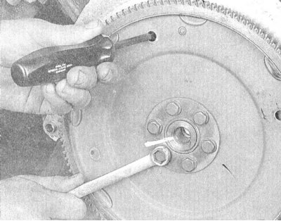
5. Loosen the flywheel/drive disk mounting bolts to the crankshaft. If the shaft starts to turn while loosening the bolts, wedge a screwdriver or pry bar between the flywheel ring teeth (manual transmission), or insert a long drift into one of the drive disk holes, resting it against the ledge on the block (automatic transmission).
6. Remove the flywheel/drive plate from the crankshaft.
Note: The flywheel/drive plate assembly is quite heavy, so it is a good idea to have an assistant help you. Wear work gloves to avoid cutting your hands on the sharp edges of the teeth on the ring gear assembly.
(The material is based on data from the portal: Nissanbook.ru)
7. Carefully wipe the flywheel with a rag soaked in acetone, completely removing traces of oil and grease. Check the working surface of the flywheel for cracks, grooves left by the heads of the clutch friction disk rivets, traces of overheating and scoring. Minor defects can be eliminated using fine-grained sandpaper. Check the toothed ring for cracks and chipped teeth. Place the flywheel on a flat surface to assess its flatness (use a flatness meter). If necessary, give the assembly a turning.
8. Wipe the mating surfaces of the flywheel/drive plate and crankshaft. If there are signs of oil leakage developing through the crankshaft rear oil seal, replace it (see section Replacing the rear crankshaft oil seal).
Installation
1. Install the flywheel/drive disk on the crankshaft, making sure that the alignment marks applied during assembly dismantling are correct.
Note. On some engines, a guide pin is provided, or the mounting holes are located asymmetrically, which guarantees an unambiguous fit of the assembly. Before screwing in the mounting bolts, lubricate the threaded part with a fixing sealant.
2. With the flywheel/drive plate locked from turning, tighten the new mounting bolts to the specified torque in a diagonal pattern.
Note: The flywheel/drive disc mounting bolts must be replaced.
3. Further installation is carried out in the reverse order of dismantling the components.