Removing
1. Remove the timing belt and timing gears (see Section Removing and installing timing belt and timing gears). Remove the oil pan (see Section Removal and installation of the pallet crankcase of the engine).
2. Remove the alternator adjustment bar and unscrew the bolt securing the bar to the oil pump (see chapter Engine electrical equipment).
3. Loosen the steering pump assembly (see chapter Suspension and steering) and slide it to the side without disconnecting the hydraulic lines. Remove the steering pump mounting bracket.
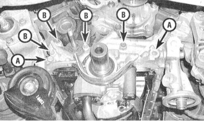
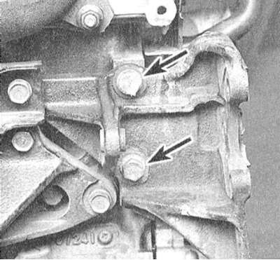
4. Turn out bolts of fastening of the oil pump to the block of the engine.
Note. The oil pickup tube with filter insert can be left connected to the pump. One of the bolts of the pump assembly is the long bolt of the alternator adjusting bar, turned out at the stage described in paragraph 2.
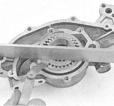
5. Tap the pump assembly through a piece of wood with a hammer to break the sealant layer.
6. Pulling outward, remove the pump from the engine block.
7. Scrape off all traces of sealant and fragments of the old gasket material from the mating surfaces of the pump and engine block, then wipe the surfaces with a rag soaked in acetone.
Examination
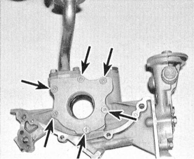
1. Using a large Phillips screwdriver, remove the oil pump rear cover screws.
2. Wash all components in solvent, then inspect them for signs of excessive wear and mechanical damage.
3. Remove the plug and remove the relief valve components. Assess the condition of the sliding surface of the valve and its spring. If defects are found, replace the components in the kit.
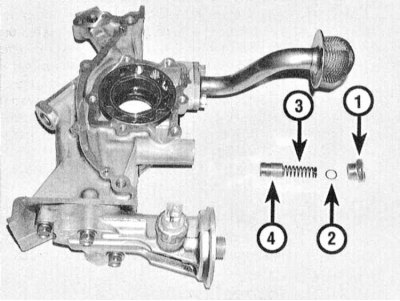
1 - Plug
2 - Washer
3 - Spring
4 - Valve
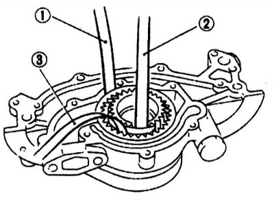
4. Using a blade-type feeler gauge, determine the working clearances of the pump gears. The following clearances must be checked:
- a) Axial backlash of landing of an internal gear wheel in the pump case;
- b) Axial backlash of landing of an external gear wheel in the pump case;
- c) Clearance between the generatrix of the outer gear and the pump housing;
- d) Clearance between the teeth of the outer gear and the sickle-shaped partition;
- e) Clearance between the teeth of the internal gear and the sickle-shaped partition;
Compare the measurement results with the requirements of the Specifications. If necessary, replace the pump assembly.
 |  |
5. Pack pump with petroleum jelly. Replace the cover and tighten the screws securing it to the required torque. Reinstall the relief valve components, screw in and tighten the plug.
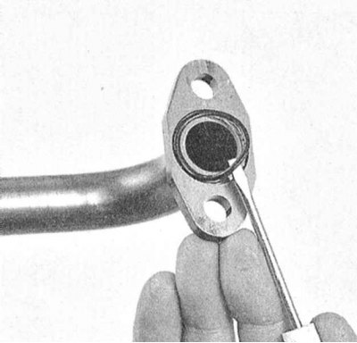
6. After replacing the O-ring, connect the oil pickup tube to the pump assembly. Tighten the tube mounting bolts to the required torque.
Installation
1. Lubricate the pump mating surface with RTV Sealant.
2. The components are installed in the reverse order of their removal. Don't forget to replace the seals.
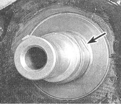
Note. The flats of the hub of the inner gear of the pump must engage with the mating flats on the crankshaft trunnion. Make sure all fasteners are tightened to the correct torque.