Removing
1. Disconnect the negative cable from the battery.
Attention! If the stereo system installed in the car is equipped with a security code, before disconnecting the battery, make sure that you have the correct combination to activate the audio system!
2. Loosen the right front wheel nuts. Apply the parking brake and support the rear wheels with wheel chocks.
3. Jack up the front of the car and place it on jack stands.
4. Remove the right front wheel and the arch protection locker (see chapter Body).
5. Remove all drive belts (see chapter Settings and ongoing maintenance).
6. Remove the crankcase protection and empty the cooling system (see chapter Settings and ongoing maintenance).
7. Remove the spark plugs (see chapter Settings and ongoing maintenance). Bring the piston of the first cylinder to the TDC position of the end of the compression stroke (see Section Bringing the piston of the first cylinder to the top dead center position (TDC)).
8. Disconnect the radiator and bypass hoses from the thermostat housing. Remove the water pump pulley.
9. Remove an intermediate roller of a belt of a drive of the K/V compressor with the arm.
10. Remove the crankshaft pulley (see Section Removal and installation of the crankshaft pulley).
Note. Do not rotate the crankshaft while removing the pulley, as this will cause the engine to move out of TDC.
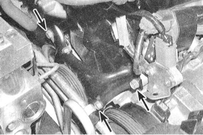
11. Release the electrical wiring and hoses from the retainers on the top cover of the timing belt.
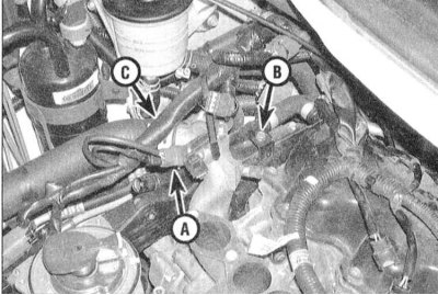
12. Remove the crankshaft trunnions, guide the timing belt, then remove the bolts securing the upper and lower belt covers. Pay attention to the fact that bolts of various sizes are used to fasten the covers, which, during assembly, must be screwed strictly into their original places - put the appropriate marking on the bolt head.
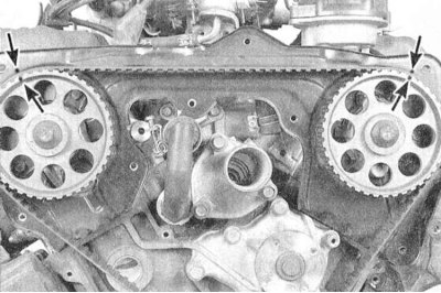
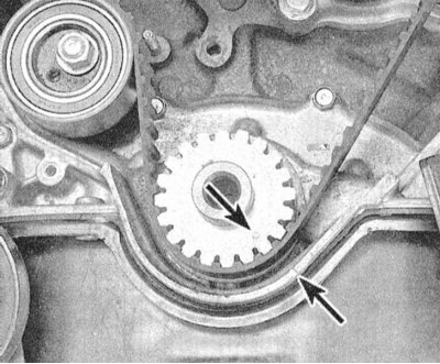
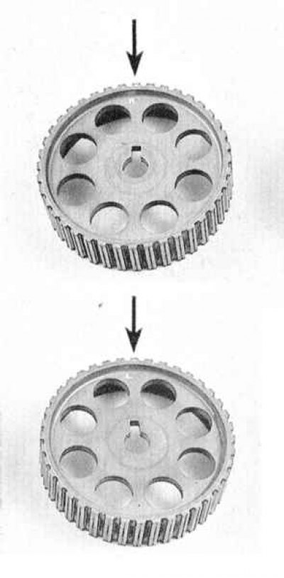
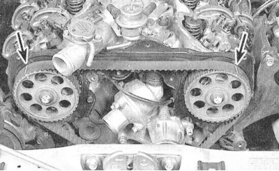
13. Make sure that the piston of the first cylinder is in the TDC position of the end of the compression stroke, - the marks on the gear wheels of the camshafts and crankshafts must be correctly aligned with the reciprocal pointers.
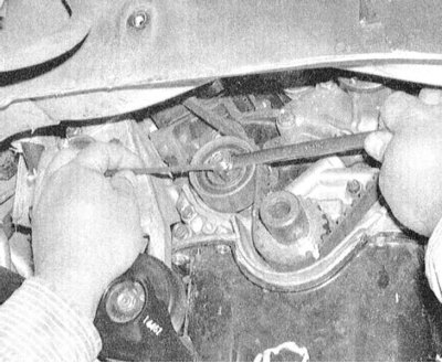
14. After releasing the lock nut half a turn and turning the tensioner 70 ÷ 80 degrees clockwise, loosen the timing belt tension force.
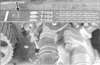
15. Check up a belt on presence on it of the marking specifying a direction of its orientation at installation on the engine. If necessary, apply the appropriate marking yourself with chalk or paint.
Note. This requirement only makes sense if the old belt will not be replaced. Remove the belt from the timing gears and carefully inspect for cracks, signs of wear, signs of oil or coolant contamination. Replace the belt if necessary. Assess the degree of wear of the tensioner assembly with the spring, make sure that the roller rotates smoothly.
16. Evaluate the condition of the gears - if there are signs of excessive wear or mechanical damage, replace the wheels.
Note. The need to dismantle the gears only arises if they are damaged, and also in order to gain access to other components, for example, when replacing cylinder heads, oil pump, front crankshaft oil seal, or rear timing belt cover.
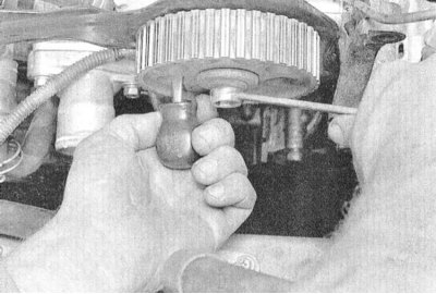
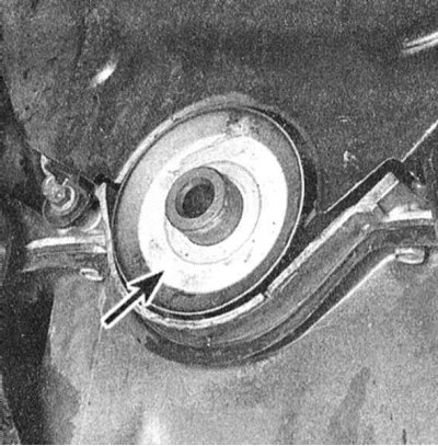
17. After passing a screwdriver through the hole in the camshaft gear, block it from turning and release the fixing bolt.
18. After the bolt has been removed, the gear wheel must be removed from the shaft journal by hand.
Note. The gear wheels of the right and left camshafts are not interchangeable and are marked accordingly.
19. Description of the procedure for replacing the crankshaft gear is given in Section Replacing the front crankshaft oil seal.
Installation
1. Make sure that the prepared new belt meets the requirements of your car engine in terms of its standard and size characteristics. New belts typically have three white markings that greatly simplify the process of fitting components and aligning them to the alignment marks.
Note. Also make sure that the geometry of the belt teeth matches the design of the timing gears. On some models of the early years of production, the lower edges of the grooves between the teeth of the wheels may have a rectangular shape, on others they are rounded. - the teeth of the belt must have an appropriate shape. Violation of this requirement leads to an increase in the noise background during engine operation and to premature wear of the belt.
2. If the tensioner was removed, reinstall it, making sure the spring is properly seated. Prepare to install the belt by turning the tensioner clockwise with a wrench. Temporarily lock the tensioner in this position by tightening the lock nut.
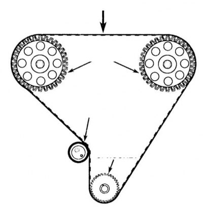
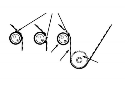
3. Following the correct alignment of the alignment marks, put the belt on the gears of the timing drive. Moving counterclockwise and being careful not to leave any slack, first put the belt on the crankshaft wheel, then put it on the wheel of the left (front) camshaft, then pull it on the wheel of the right (rear) camshaft. Finally, slide the belt under the tensioner pulley.
4. Manually take up some slack in the belt from the tensioner side, then loosen the nut of the tensioner and turn the assembly 70 ÷ 80 degrees counterclockwise. Tighten the lock nut. Make sure that all three sets of alignment marks are correctly aligned, and that the belt is put on with the correct side forward.
5. Slowly turn the crankshaft clockwise two full turns, finally returning it to the TDC position of the end of the compression stroke.
Attention! Excessive resistance of the shaft to turning indicates that the pistons are in contact with the valves and, before continuing to turn the shaft, you should return to its original position and make an appropriate adjustment to the TDC position.
6. Tight (with a force of about 10 kgf) pressing the belt in the area exactly in the middle between the gears of the camshafts, measure the amount of its deflection. The required value must lie between 13 and 15 mm.
7. If the deflection is within the allowable range, the belt tension force can be considered adjusted correctly, otherwise, loosen the tensioner lock nut and make appropriate adjustments (see below).
Note. When adjusting the belt tension, the help of an assistant will not be superfluous.
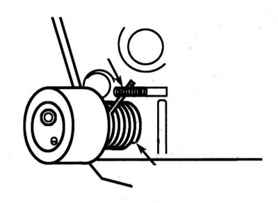
8. Insert a 0.35 mm thick feeler blade into the gap between the belt and the tensioner roller in accordance with the diagram shown in the illustration - to retract the feeler under the belt, slowly turn the crankshaft clockwise.
9. While pressing the tensioner firmly against the feeler blade with a bar wrench, tighten the lock nut.
10. After turning the crankshaft, release the feeler blade from under the belt, then turn the shaft further a full two turns, finally returning it to the TDC position of the end of the compression stroke.
11. Make sure that the belt tension force is adjusted correctly.
Note. If it is not possible to achieve the required tension force of the used belt, it should be replaced.
12. Install the remaining components in the reverse order of their dismantling.