


Table of contents: Injection engines ↓ Carburetor engine ↓
Although the ignition timing is adjusted automatically, it can also be adjusted manually. The preparatory work is the same as the idle adjustment for the corresponding engine. The ignition is adjusted when the engine is idling. Different engines require different work.
Injection engines
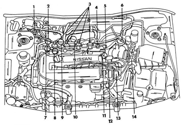
Position of individual components of the fuel injection system and ignition system in the engine compartment of a vehicle with an SR20DE engine
1 - adsorber; 2 - additional air valve; 3 - injection valves; 4 - fuel pressure regulator; 5 - throttle position sensor; 6 - fuel filter; 7 - switching valve, idle speed adjustment; 8 - coolant temperature sensor; 9 - air regulator; 10 - resistor; 11 - transistor; 12 - ignition coil; 13 - crankshaft angle sensor; 14 - air flow meter
Before checking and adjusting, certain conditions must be met to obtain accurate results, i.e. those mentioned in Chapter Routine care and maintenance parts or systems must be checked and adjusted accordingly. The idle speed must correspond to the required value.
After warming up the engine and connecting the tachometer and stroboscope, do the following:
1. With the engine off, locate the throttle position sensor (see illustration) and disconnect the plug. Start the engine.
2. Increase the engine speed to 2000 - 3000 rpm two or three times and then let it idle for 2 minutes.
3. Read the tachometer. The engine should be running at 800 rpm.
4. Read the ignition timing in the stroboscope beam on the crankshaft belt pulley. If the ignition timing is outside the range of 15±2° before TDC, adjustment is required. To do this, loosen the distributor mounting bolts (see Fig. illustration) and turn the distributor until the correct ignition timing is obtained. When re-adjusting, you should always aim for an exact value of 15°. Retighten the bolts and check the ignition timing.
5. Finally, reconnect the plug.
Note: On vehicles without a catalytic converter, the ignition timing adjustment is carried out in the same way. The crankshaft pulley has a notch on the edge to show the ignition timing adjustment from the outside. There is an adjustment plate on the camshaft drive cover and each division corresponds to 5°. On illustrations the ignition timing marks are shown.
Carburetor engine
On cars with carburetor engines, the work differs depending on whether a catalytic converter is installed or not.
With catalyst
Before the ignition timing can be checked, the steps given in Chapter Routine care and maintenance conditions.
1. Warm up the engine, i.e. the remote thermometer pointer should be in the middle position. When adjusting, the engine should maintain operating temperature, i.e. during pauses, the engine may need to be started to warm it up again. The engine should operate at a speed of less than 1000 rpm.
2. Connect the tachometer and stroboscope according to the instructions.
3. Accelerate the engine two or three times to 2000-3000 rpm and then let it idle for a minute.
4. Read the idle speed reading on the tachometer.
5. The engine should operate at a speed of 750±50 rpm. If the value does not correspond to the required value, the idle speed should be adjusted in advance. The necessary work is described in Chapter Routine care and maintenance.
6. Read the ignition timing in the strobe light beam on the crankshaft belt pulley. If the ignition timing is outside the limits specified in Specifications at the beginning of the Chapter, an adjustment must be made. The illustration below shows where the ignition timing can be read in the strobe light beam.
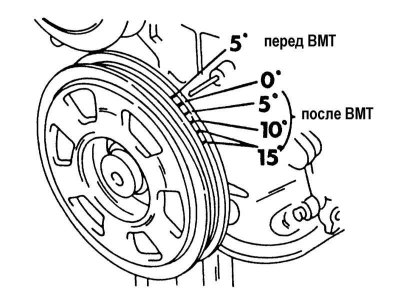
View of the ignition timing marks on the crankshaft pulley. The "0" mark is marked in yellow.
7. When adjusting the ignition timing, it should be adjusted to different values. In the place shown in the illustration, you can see the installed sensor for the boost pressure (on the right side of the car, standing in front of the engine compartment, near the shock absorber suspension). This device monitors the vacuum in the intake manifold and sends an electrical signal to the electronic control unit. Since this affects the ignition timing, it must be turned off. To do this, remove the vacuum hose and insert a bolt of the appropriate diameter into its end.
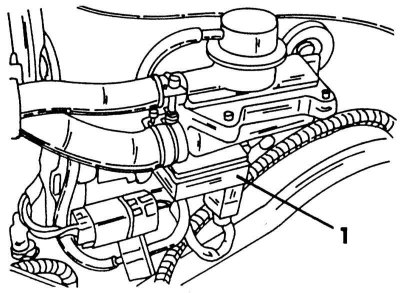
Position of the booster pressure sensor (1).
8. Loosen the distributor mounting bolts and turn the distributor until the "0" and "5" marks are approximately opposite the pointer when illuminated by a strobe light. Tighten the bolts again.
9. Put on the hose and check the ignition. This time the value from Specifications at the beginning of the Chapter. The data provided must be studied thoroughly, since there may be two different ignition distributors and the adjustments are slightly different from each other.
Note: Adjusting the ignition timing on vehicles without a catalytic converter is done in a similar manner.
Without catalyst
On an engine without a catalytic converter, adjustment is somewhat more complicated, since, depending on the distributor installed, the vacuum hose must either be disconnected from the carburetor and closed, or remain connected. To plug the hose, insert a bolt of the appropriate diameter into its end. More precise instructions are given in Specifications at the beginning of the Chapter. According to them, the ignition timing has different values. Otherwise, the adjustment is carried out in the manner described for catalytic models.