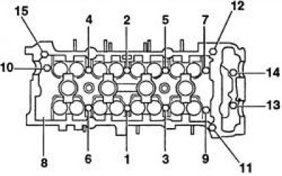
Cylinder head bolt tightening sequence
Removing
1. Disconnect the battery from the ground.
2. Remove the chains.
3. Remove both camshafts.
4. To facilitate the dismantling of the head, it is recommended to remove both manifolds (see subsection 6.1.12 and subsection 6.1.13).
5. Disconnect the muffler downpipe from the manifold.
6. Remove the air filter (see subsection 6.1.2). 7. On carburetor engines, do the following:
- disconnect from the fuel pump fuel hoses;
- disconnect the throttle cable;
- disconnect the wiring connectors from the carburetor;
- disconnect the hoses of the vacuum brake booster, cooling system, suction inside crankcase gases and other hoses from the corresponding valves and pipes of the cylinder head;
- remove the suction manifold stand;
- on vehicles equipped with a catalytic converter, disconnect the connector from the oxygen sensor.
8. On injection engines, perform the following work:
- perform measures to decompress the fuel system and disconnect the fuel hoses from the fuel distributor;
- disconnect the throttle cable;
- disconnect the wiring connectors from the throttle chamber, intake manifold and other parts and assemblies;
- disconnect the hoses of the vacuum brake booster, cooling system, suction inside crankcase gases and other hoses from the corresponding valves and pipes of the cylinder head;
- remove the manifold stand;
- on vehicles equipped with a catalytic converter, disconnect the connector from the exhaust gas sensor.
9. Disconnect the cooling system hoses from the cylinder head.
10. Remove the M6 bolt in the front left corner of the cylinder head.
11. Working in the reverse order shown in Fig. Cylinder head bolt tightening sequence, loosen all ten main cylinder head bolts. Loosen the bolts in several steps, 1/2 turn per step, until the bolts can be turned away by hand.
12. Remove the bolts and washers, paying attention to their orientation.
13. Working with two people, remove the cylinder head, gasket, dowel pins and oil nozzle (if the fit of the pins and the nozzle is loose).
14. If the head will be disassembled for overhaul, then follow the description in section 3.1.2.6.
Assembly preparation
1. Check up a condition of carvings of bolts of fastening of a head of cylinders, irrespective of the reason of removal of a head. Bolts are recommended to be changed each time the cylinder head is removed.
2. Clean the split surfaces of the head and block, covering all holes to prevent dirt from entering. Lubricate the gaps in the pistons with grease, which then remove.
3. Check for damage on the split surfaces of the cylinder head and block (deep scratches, chips, etc.). Minor damage is removed with a needle file, serious damage is removed only by grinding.
4. Check the deformation of the split surfaces of the head and block.
Installation
1. Wipe dry the split surfaces of the head and cylinder block. Make sure there are guide pins on both sides of the plane of the cylinder block and insert the oil jet into the center of the block.
2. Place a new gasket on the cylinder block, aligning the holes in the gasket with the pins and oil jet.
3. With an assistant, carefully place the head on the cylinder block, aligning the head with the guide pins.
4. Lubricate threads and undersides of bolt heads with clean oil.
5. Place the washers on the bolts so that the conical surface of the washers is facing away from the bolt head.
6. Carefully insert the bolts into the appropriate holes in the head (do not drop bolts), hand-tighten.
7. Tighten bolts 1–10 of a head of cylinders in the specified sequence (see fig. Cylinder head bolt tightening sequence) with the torque of the 1st stage of tightening. Bolts 11–15 with M6 thread do not tighten yet.
8. Tighten the bolts to the torque of the 2nd stage.
9. After a minute, and release the bolts in the reverse order indicated in fig. Cylinder head bolt tightening sequence. Loosen the tightening gradually, 1/2 turn at a time, until the bolts begin to turn away by hand.
10. Following sequence, tighten bolts with the moment of the 3rd stage of an inhaling.
11. Tighten the bolts to the angle of the 4th stage of tightening or tighten with a torque wrench to the torque of the 4th stage.
12. Following the sequence, tighten the M6 bolts (bolts 11–15) with a given moment.
13. Connect the cooling system hoses.
14. Perform the following operations:
- attach the removed wiring, hoses and cables on the suction manifold;
- attach the throttle cable;
- connect the muffler downpipe, exhaust gas sensor connector (if provided);
- Install the air filter and air duct.
15. Install camshafts (see subsection 3.1.1.10).
16. Install chains and sprockets.
Attention! If the cylinder head has been overhauled, check the valve clearances on a cold engine before installing the cylinder head cover (see subsection 3.1.1.9).
17. Start the engine and warm up. Check valve clearances on a warm engine (see subsection 3.1.1.9).