Camshaft drive parts
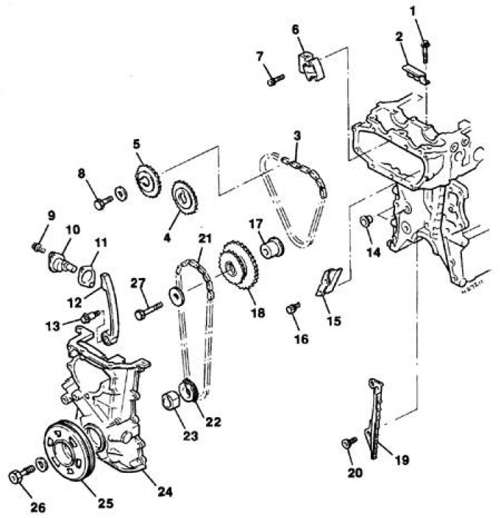
1. Upper chain guide bolt; 2. Top guide; 3. Top chain; 4. Exhaust camshaft sprocket; 5. Intake camshaft sprocket; 6. Upper chain tensioner; 7–9. Bolt; 10. Lower chain tensioner; 11. Gasket; 12. Shoe; 13. Shoe axle bolt; 14. Guide pin and gasket; 15. Upper chain damper; 16. Bolt; 17. Roller intermediate sprocket; 18. Intermediate sprocket; 19. Lower chain damper; 20. Bolt; 21. Bottom chain; 22. Leading sprocket; 23. Shaped sleeve oil pump; 24. Chain cover; 25. Pulley; 26. Pulley bolt; 27. Bolt
Attention! If the cover is removed without violating the fastening and integrity of the cylinder head seal, then after assembly, a slight oil leak from under the gasket installed between the cover and the cylinder head is possible. Therefore, it is advisable to combine the removal of the cover with the removal of the cylinder head and the replacement of the gasket.
Removing
1. Remove the coolant pump (see subsection 4.7).
2. Remove crankshaft pulley (see subsection 3.1.1.5).
3. Remove the oil pan and oil receiver with coarse filter (see subsection 3.1.1.12).
4. Remove the two bolts securing the power steering pump bracket to the chain drive cover, nuts and bolts securing the bracket to the pump, and remove the bracket.
5. Remove the bracket from the power unit support by unscrewing the three bolts and releasing the wiring from the clamps on the bracket.
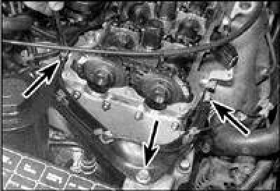
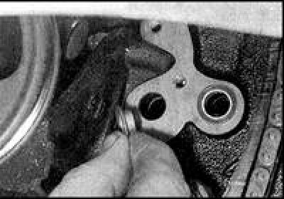
6. Remove bolts and nuts (indicated by arrows) and remove the timing gear inspection cover from the right side of the cylinder head. Remove the gasket.
7. Turn away two bolts and get a tensioner of the lower chain. Remove the tensioner gasket, paying attention to its orientation.
Attention! When removing the chain tensioner, rotation of the crankshaft is not allowed.
8. Remove the four bolts securing the cylinder head to the top of the chain drive cover. On early production vehicles, you will need to remove the top chain guide to access one of the bolts.
9. Raise the engine with a jack or hang it on the hoist of the lift, hooking the hoists to the special lugs on the engine.
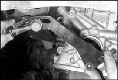
10. Turn away a coupling bolt of the right support of the power unit, then turn away three bolts and remove a support. If the rubber pads of the supports have fallen behind the body bracket, then remove the pads as well.
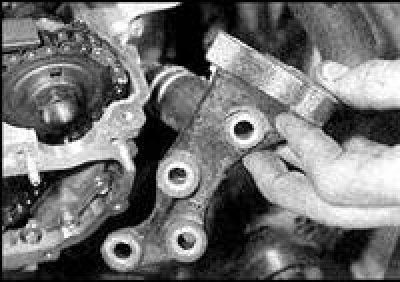
11. Turn away bolts of fastening of an arm and a bolt of fastening of an adjusting bracket of the generator to an arm. Remove the right support bracket.
12. Loosen the chain cover bolts. The bolts are of different lengths, so mark their original position.
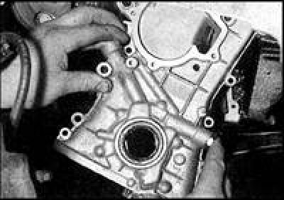
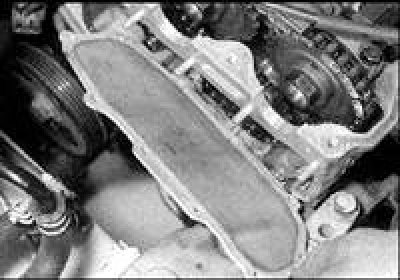
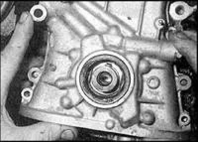
13. Remove the cover from the toe of the crankshaft, then by manipulating, remove the cover from the engine compartment. Remove the oil channel seals, they must be replaced. If the lid guide pins are loose, remove them and store with the lid.
14. Remove the oil pump drive gear bushing from the crankshaft toe.
Installation
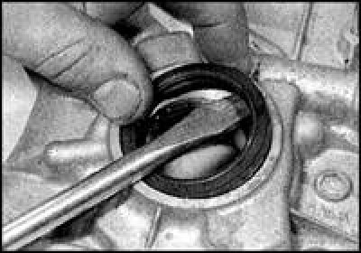
1. Before installation, it is recommended to replace the crankshaft oil seal.
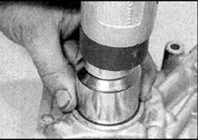
2. Press the new oil seal into the collar until it stops. Press in with a mandrel resting only on the outer edge of the stuffing box.
3. Make sure the sealing surfaces of the cover and cylinder block are clean and dry.
4. Insert new sealing sleeves into the oil channels of the cylinder block.
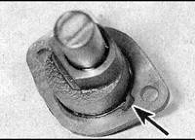
5. Apply a thin layer of sealant to the split surface (arrow) covers with the cylinder block, apply sealant to the area around the coolant pump channel in the central part of the cover. If the cylinder head was not removed, then also apply sealant to the upper plane of the cover.
6. Insert the guide pins into the cylinder block.
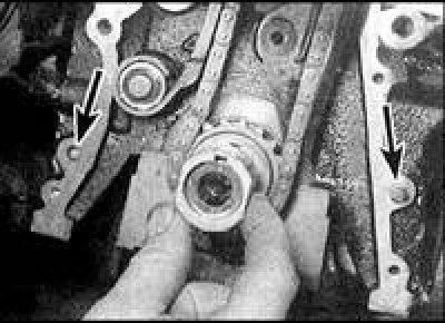
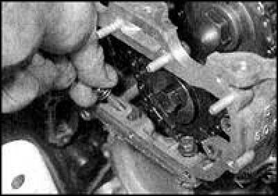
7. Align the keyway in the oil pump bushing with the key, then slide the bushing over the crankshaft toe (arrows indicate guide pins).
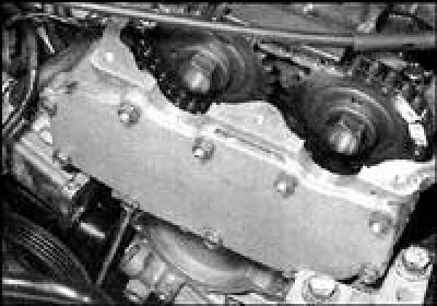
8. Raise the cover and align the oil pump drive gear so that the gear engages the shaped bushing when the cover is in place. Put the cover on the crankshaft, being careful not to damage the sealing lips, install the cover on the guide pins.
9. Screw the cover bolts into the previous holes, tighten the bolts in several stages, gradually increasing the tightening torque.
10. Wrap four bolts M6 of fastening of a head of the block of cylinders to a cover, tighten bolts with the set moment. On older engines, install the top rail.
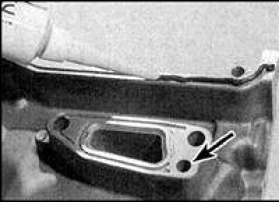
11. Install a new gasket on the lower chain tensioner, orienting it so that the notch on the gasket is aligned with the oil hole of the tensioner (indicated by an arrow). Install the tensioner with gasket and tighten the bolts to the specified torque.
12. Establish an arm of the right suspension bracket of the power unit, tighten bolts with the set moment. Lay the rubber pads into the suspension bracket on the body side (if you got), making sure that the pad pins fit into the holes in the bracket. Install the support and tighten the bolts to the specified torque.
13. Align the right power unit support with the body bracket, insert the tie bolt and tighten the nut to the specified torque. Remove the hoist from the engine (or remove the jack).
14. Make sure that the sealing surfaces of the camshaft driven sprocket inspection cover and cylinder head are clean and free of moisture and oil. If a gasket was installed on the cover, then replace the gasket by installing it on the cylinder head. If the seal was provided with sealant, then apply sealant around the entire perimeter of the cover. Install the cover and tighten the bolts and nuts to the specified torque.
15. Install the bracket on the right support of the power unit and tighten the bracket bolts to the specified torque.
16. Install the power steering pump to the engine and tighten the pump bracket bolts.
17. Install an oil receiver with a coarse filter and an oil pan (seesubsection 3.1.1.12).
18. Install the crankshaft pulley (see subsection 3.1.1.5).
19. Install coolant pump (see subsection 4.7).
20. Fill the engine with oil and coolant.