Tightening sequence of the camshaft bearing cap bolts
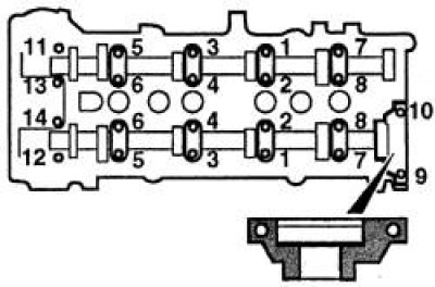
Apply sealant to the shaded areas of the left exhaust camshaft cover before installing.
Removing
1. Remove the ignition distributor.
2. Remove the camshaft sprockets.
3. The covers for the front and rear camshaft bearing journals are different from the other bearing journals. On cars of later releases, identification symbols are cast in the upper part of the covers (for exhaust camshaft E2, E5, intake valves - I2, I5). On cars of early releases, numbers on the covers of the camshaft bearing journals may be absent, therefore, before removing them, labels must be applied that should indicate the serial number and orientation of the cover.
4. Loosen the bolts securing the camshaft bearing journals, working in the reverse order to that shown in the diagram. Loosen the bolts in several steps, one turn at a time. After the springs are completely released, the bolts can be completely unscrewed. Remove the front and rear covers first, then the exhaust camshaft covers. Remove the intake camshaft covers last.
5. Take out the distributors.
6. Place pushrods and shims in separate numbered bags.
Examination
1. Examine working surfaces in covers and in a head of cylinders. Check for burrs and signs of deep wear. Check for metal chipping on the camshaft cams (areas of bluish tint), deep development, chips formed due to wear.
2. Check the runout in the middle neck of the camshaft. If the runout is greater than normal, replace the camshaft.
3. Using a micrometer, measure the dimensions of each of the camshaft cams and compare with the standard ones. Replace camshaft if excessive wear or damage occurs.
4. Check the clearance in the camshaft bearing journals. This can be done in two ways, either by direct measurement or by using a plastic gauge.
5. When measuring the clearance directly, install the camshaft bearing journal caps into the cylinder head in the same order and orientation. Tighten the cap bolts to the specified torque in the sequence shown in the diagram.
6. Measure the inner diameter of the bearing surfaces of the covers and compare with the normative ones. If the inner diameter in any cover exceeds the limit, then replace the cylinder head. The clearance can be defined as the difference between the inner diameter of the journal hole with the cover installed and the diameter of the camshaft bearing journal.
7. When measuring the clearance with a plastic gauge, clean both camshafts and the bearing surfaces of the journals in the cylinder head and in the covers. Lay the camshafts in the cylinder head.
8. Lay pieces of plastic gauge wire along the bearing surfaces of the journals of the camshafts parallel to their axis, taking measures to prevent rotation of the camshafts, install the camshafts and tighten the covers (see below).
9. Loosen the cap screws and carefully remove the caps without turning the camshafts.
10. Compare the maximum width of the crushed wire from each neck with the scale on the gauge package.
11. Compare the measurement result with the standard. If the gap exceeds the norm, then measure the diameter of the camshaft journal with a micrometer. If the diameter is less than the maximum allowable, then replace the camshaft and check the clearances in the bearing journals again. If the clearance is still too high, replace the cylinder head and bearing journal covers.
12. Check for signs of wear on the tappets and the inside surfaces of the cylinder head. If the necessary measuring instruments are available, then the degree of wear can be estimated by the difference in the diameters of the pusher and the hole in the cylinder head. Compare the resulting clearance with that specified in subsection 3.1.1.1. Replace worn parts if necessary.
Installation
1. Liberally lubricate the tappets and tappet bores in the cylinder head. Carefully insert the pushers without disturbing the original order of their installation. When installing, the pusher must be inserted into the hole without distortion. Insert the shims into the tappets, make sure they are installed correctly, then generously lubricate the bearing journals and camshaft cams.
2. Install camshafts. The exhaust camshaft can be easily identified by the distributor drive splines on the left side.
3. Make sure the groove on the crankshaft pulley is aligned with the pointer on the front cover. Orient the camshafts so that the cams of the 1st cylinder are facing away from the respective valves. With the camshafts in the correct position, the locating pin of the intake camshaft sprocket at the front of the camshaft should point to 9 o'clock (viewed from the right side of the engine), and the exhaust camshaft locating pin must be in the upper vertical position (at 12 o'clock).
4. Make sure that the contact surfaces of the bearing neck covers and cylinder head beds are absolutely clean, that there are no scratches or traces of oil on these surfaces. Apply a thin coat of sealant to the contact surfaces of the leftmost cover of the exhaust camshaft bearing journal.
5. Install the covers of the support necks, guided by the marks applied during removal (or available).
6. Tighten the cover bolts in the sequence shown in the diagram. Tighten the bolts evenly, gradually increasing the force, turning the bolts one turn at a time, until the covers come into contact with the cylinder head. Then tighten the bolts to the specified torque. Tighten only in the order shown to ensure an even and gradual increase in force from the valve springs on the bearing journal covers.
7. Install the camshaft sprockets.
Attention! If the cylinder head and camshafts have been overhauled, check the valve clearances on a cold engine before installing the cylinder head cover.
8. Install the ignition distributor.
9. Check valve clearances.