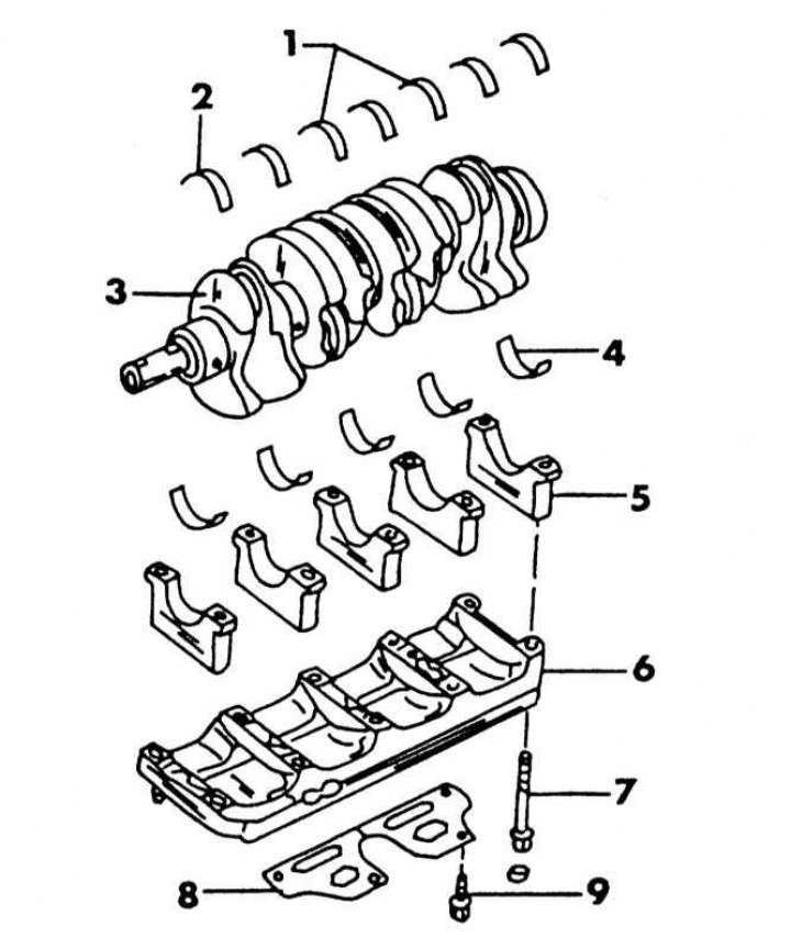
Injection engine crankshaft bearings
1 - adjusting half rings; 2 - upper liners of main bearings; 3 - crankshaft; 4 - lower liners of main bearings; 5 - covers of main bearings; 6 - frame of main bearing caps; 7 - cover bolts; 8 - oil-conducting plate; 9 - bolt, 6.5-7.5 Nm
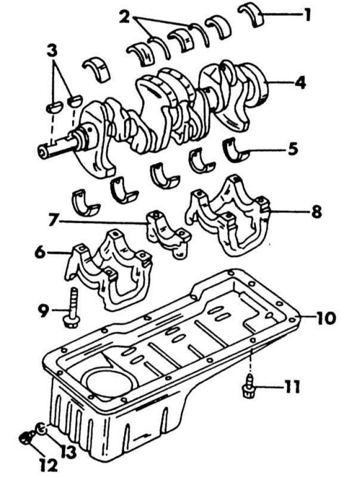
Supports of the crankshaft of the carburetor engine
1 - upper liners of main bearings; 2 - adjusting half rings; 3 - segment keys; 4 - crankshaft; 5 - lower liners of main bearings; 6 - front cover of the main bearing; 7 - middle cover of the main bearing; 8 - rear cover of the main bearing; 9 - cover bolt, 47-53 Nm; 10 - oil pan; 11 - bolt, 6.5-8.5 N·m; 12 - oil drain plug, 30-40 Nm; 13 - gasket
The crankshaft supports of the injection and carburetor engines are different. In a carburetor engine, the crankshaft has five bearings. Double bearing caps are used at both ends. The injection engine uses five main bearing caps, however, a cap frame is installed on the caps to maintain their position. The illustrations above show both versions of the crankshaft bearings.
Measurement of crankshaft end play
Before removing the crankshaft from the installed engine, measure the axial play in order to know whether it is necessary to replace the adjusting half rings on the middle support during assembly. Proceed as follows:
1. Install a dial indicator in front of the end of the flywheel as shown in the illustration and check if the end play is less than 0.3mm. This is the maximum allowable backlash. First, the dial indicator should be set to "0".
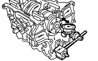
Measurement of the axial play of the crankshaft. Measurements on both engines are carried out in the same way
2. Lever resting on the shoulder of the crank (better wooden handle tool) press the shaft to the side as shown by the arrow in the illustration.
Removing the crankshaft
To remove the crankshaft, the engine must be removed. In chapter Engine disassembly most of the preparatory work is described, which are detailed in the following chapters:
1. Remove the cylinder head (Chapter Cylinder head and timing gear).
2. Remove the oil pan (Chapter Cooling and heating systems).
3. Remove the camshaft drive (Chapter Cylinder head and timing gear).
4. Remove the flywheel, engine intermediate plate and stuffing box flange from the back.
5. Remove pistons and connecting rods.
6. On the injection engine, guided illustration, loosen the bolts of the main bearing caps from the edge to the middle (first loosen both bolts on the flywheel side) and remove the bed caps main bearing caps and nested liners. Label each cap and insert (colored stripe), so that they can be reinstalled in their original position. Raise the crankshaft and remove the upper halves of the main bearing shells from the cylinder block. Stack the liners with other liners and matching caps. Mark both adjusting half rings and remove from the middle support.
7. On a carbureted engine, guided illustration Loosen the three bearing caps in the sequence shown in the illustration below in several passes and remove the caps in order. Remove the crankshaft as described for an injection engine.
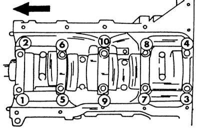
The sequence of loosening the bolts of the crankshaft main bearing caps on a carburetor engine.
Crankshaft oil seals
The front oil seal is located in the camshaft drive cover, the rear oil seal is located in a flange screwed to the cylinder block. Both seals can be replaced on an installed engine. Depending on the version, the front cover can either remain installed or must be removed.
Replacing the front crankshaft oil seal
1. On the injection engine, unscrew the bottom panel, the cover in the right wheel arch and the side cover of the engine and remove the crankshaft belt pulley. Carefully pry out the seal with a screwdriver.
2. On the carburetor engine, remove the drive belts and all parts installed on the end side of the engine, as described in Section Cylinder head and timing gear, so that the camshaft drive cover can be unscrewed. Remove the seal from the front with a screwdriver. Do not damage the cover while doing this.
Shift into gear to hold the crankshaft pulley.
3. Drive in a new oil seal with a suitable rod (in both cases outside). Lubricate the working edge with a small amount of lubricant. Depending on the engine, install either the cover or the removed parts. Depending on the installed units, adjust the drive belts after assembly.
Replacing the rear crankshaft oil seal
1. Remove the gearbox, flywheel and clutch (or in the variant with automatic transmission drive plate).
2. Loosen the sealing flange bolts and remove the cover. Carefully clean the sealing surfaces of sealant residues with a scraper. With a little dexterity, the stuffing box can be removed from the installed cover.
3. Knock out the stuffing box from the inside out without damaging the housing. To do this, use a reliable sharp mandrel.
Installation is carried out as follows:
4. Carefully hammer in the new oil seal to center it. In doing so, do not damage the working edge. The outer surface of the gland must be flush with the housing.
5. Coat the stuffing box with sealant and reinstall the bonnet.
6. Perform all other work in the reverse order of removal.
Checking crankshaft parts
1. Carefully check the crankshaft for damage and accurately measure the main and connecting rod bearings. The journals of the main and connecting rod bearings can be ground to allow the shaft to be fitted with oversized bearing shells.
2. Clamp the crankshaft between the centers of the lathe or put the outer trunnions into prisms (see illustration below) and check the runout on the middle neck with a dial indicator. The runout should not exceed 0.04 mm. It should be remembered that the runout reflected on the indicator during one revolution of the crankshaft must be divided by 2 in order to obtain a valid bend. If the runout is greater, the shaft should be replaced.

Carefully remove the oil seal from the camshaft cover using a screwdriver.
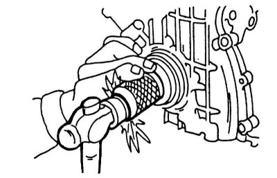
When clogging the front gland, the rod must be installed on the entire outer surface.
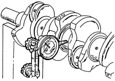
Checking crankshaft runout. Install a dial indicator on the middle journal of the main bearing and slowly rotate the crankshaft mounted in prisms.
Measuring the clearance of main and connecting rod bearings
Bearing clearance is usually measured using a polymer hair "Plastigage", however, accurate measurement of the bearing journal diameter and the inner diameter of the bearing shells is recommended on these motors. When determining the bearing clearance, proceed as follows, provided that the outer and inner micrometers are available:
1. Clean the bearing shells well and insert into the bearing bores of the cylinder block (according to bearing designations). Insert the lower shells into the main bearing caps and install the caps onto the crankcase. Screw on the cover frame on the injection engine.
2. Tighten all the bolts of the main bearing caps, starting from the inside outward, with the appropriate Specifications tightening torque (see illustration for carburetor, illustration for injector).
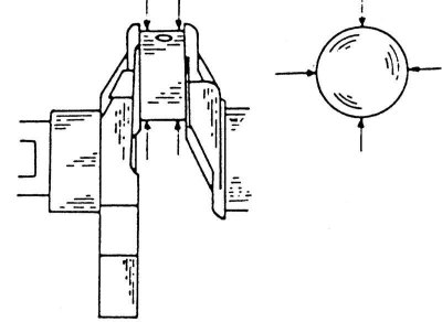
3. Using an internal indicator, measure the inside diameter of the individual bearings as shown in the illustration. In this case, first install the measuring probes as shown in the illustration, then at a right angle to this. Record the values obtained for each bearing and each direction of measurement. Difference between measurements "A" And "IN" gives oval holes.
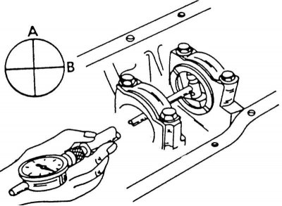
Measuring the inner diameter of bearing shells with caps installed. Take measurements in directions "A" And "IN". Also on both outer edges of the bearing.
4. Referring to the illustration below, measure the diameter of each bearing journal. At the same time, take measurements in the directions "A" And "IN", as well as in places "1" And "2". Difference between measurements "A" And "IN" reflects the ovality of the neck; difference between measurements "1"And "2" reflects narrowing of the neck. Write down the dimensions for each neck and each measurement location.
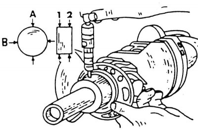
Measurement of crankshaft bearing journals. Measure the diameter in places "1" And "2", as well as in directions "A" And "IN".
5. Calculate the difference between the values "A-B" And "1-2". If the ovality or taper is out of tolerance, the necks must be ground. If the values are correct, subtract the outer diameter of the main bearing journal from the inner diameter of the same bearing. The result will give a gap whose value is specified in Specifications.
6. Calculate all clearances as described above. If the clearances of any bearing have reached the limit value, the crankshaft should be ground to install the oversized bearing shells.
7. The same measurements should be made on the connecting rod journals and bearings. Tighten the connecting rod bearing nuts to the appropriate Specifications tightening torque (to do this, clamp the connecting rod in a vice and measure the bearing journals), as well as the inner diameter of the liners according to the two illustrations below.
Measuring the necks of connecting rod bearings. The measurement should be made at the places marked with arrows.
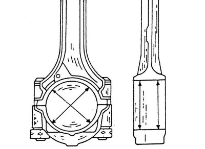
Measuring the inside diameter of the connecting rod bearings. Measurements should be made at the places marked with arrows.
8. Calculate the bearing clearances as described above and, based on the results, determine the condition of the journals. If the neck play has exceeded the limit value, the crankshaft must be ground. Choosing the right bearing shells is a tricky job and it is recommended that you refer to the following guidelines when contacting your parts supplier to select the correct bearing shells for the main and connecting rod bearings.
9. In the cylinder block, at the place indicated in the illustration, numbers are stamped that indicate the class of crankshaft bearings. The same numbers are stamped on the counterweight of the crankshaft. When looking at the crankshaft from the front, the size class of the first bearing is on the left when it comes to an injection engine. Numbers from 0 to 4 are used.
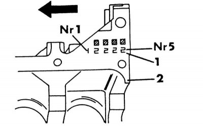
The cylinder block at the indicated location has designations for the dimensions of the journals of the main bearings
1 -class number
2 - cylinder block
10. For a carbureted engine, the opposite is true, i.e. viewed from the front, the number stamped on the left is bearing number 5. This engine uses only the numbers 0 to 2. To correctly order color-coded liners, copy the numbers on the cylinder block and the numbers on the crankshaft and provide them to your supplier. Thanks to this, the seller can pick up the parts you need. If the shaft has been ground, you will automatically receive the required liners.
11. A similar sizing occurs for connecting rod bearing shells, which are identified based on four digits.
Installing the crankshaft
Guided by various wiring diagrams:
1. Install the engine with the crankcase side facing up. Insert the upper halves of the crankshaft bearing shells into the holes. Inserts with oil holes are installed in the block. To the left and to the right of bearing No. 3, install both adjusting half rings. If new bearing shells are installed, they must be installed in the appropriate holes according to the color code. The guide tabs of the bushings must fit into the corresponding holes. Lubricate bearing surfaces well.
2. Carefully lower the crankshaft into the supports.
3. Lubricate well and install the bearing shells on the journals, following the instructions above.
4. Install covers on bearings.
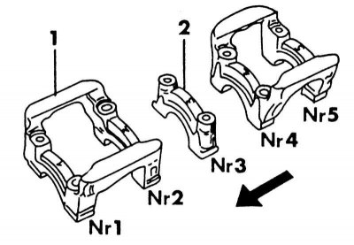
Bearing caps of the crankshaft of a carburetor engine. The lower numbers indicate where the covers are installed. Big arrow pointing forward
1 - bearing cover
2 - embossed arrow
In doing so, keep the following in mind:
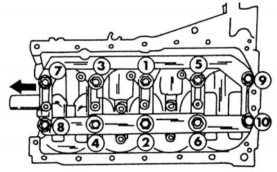
The sequence of tightening the main bearing caps of the injection engine. The arrow points forward.
- For carbureted engines, follow the illustration and fit the covers accordingly. All caps have an arrow that must point forward when installed. Insert the cover bolts and, as shown in illustrations, tighten to 47 - 53 Nm in two or three passes. Move the crankshaft from side to side several times before tightening the bolts so that the crankshaft sits in the liners.
- On the injection engine, install the bearing caps according to the designations and install the cap frame on top. Tighten the bolts in the sequence shown in the illustration in two or three passes to 33 - 39 Nm. Then tighten them in the same sequence with a final torque of 75 - 85 Nm.
5. Check the end play using a dial indicator as described in subsection Measurement of crankshaft end play. If the axial play does not meet the required value, it means that the measurements were not carried out accurately enough during the repair.
6. Screw on the stuffing box from the back. Cover the sealing surface with sealant.
7. Install pistons (Chapter Pistons and connecting rods).
8. Screw on the rear motor intermediate plate.
9. Install the flywheel or torque converter drive plate and tighten the bolts to the correct Specifications effort. The flywheel or disc must be kept from turning, which is best done by inserting a wooden block between the crankshaft and the flywheel. Use only well-threaded bolts, lightly lubricate the threads with oil.
10. Further assembly is carried out in the sequence already described, i.e. the cylinder head, timing gear drive, oil pan, etc. are installed. according to the instructions in the individual sections. Installation of the pallet of a case is considered in the Chapter Engine Assembly.