Note. To perform the procedures described below, you will need a voltmeter and ammeter with a measurement range of 80-0-80 A.
1. Pay attention to the polarity of the battery connection (see tables of sizes and adjustments at the end of the guide).
2. Do not short or ground the common terminals with the charging circuit.
3. Disconnect the battery before connecting the charger.
4. When using an auxiliary battery, connect it in parallel, i.e. plus to plus, minus to minus to keep the total output voltage at 12V.
5. Never disconnect the battery or charging circuit terminals while the engine is running.
6. Regularly check the condition and tension of the drive belt (to her).
7. Keep the battery terminals clean and secure all contact connections.
8. When performing electric welding work on a car, be sure to turn off the battery and generator.
Vehicle check
Note. If the charge warning light remains on after starting the engine and setting the engine speed to 1,000 rpm, or if there is reason to suspect a battery level malfunction in one direction or another, perform a series of checks listed below.
1. Stop the engine.
2. Check that the drive belt tension is correct (to her).
3. Check the condition of the fuse link.
4. Strip the battery terminals. Tighten all contact connections, checking the wiring for a short circuit.
5. Check the battery level. If it is low, recharge the battery or replace it.
6. Start the engine and warm it up to normal operating temperature.
7. Stop the engine and disconnect the negative cable from the battery.
8. Give a nut of fastening of the output plug (BAT) generator (the accompanying illustration shows a 4.2L engine alternator), remove the washer and disconnect the generator output wire.
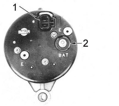
1 - connector terminals
2 - output terminal
9. Connect one of the 80-0-80 ammeter wires to the generator output terminal, the other to the output wire.
Note. Do not use clamps of the type "crocodile". Bolt clamps or special clamps should be used - accidental disconnection of wires during testing can lead to failure of the generator diode assembly.
10. Connect the negative wire to the battery, turn on the voltmeter between the battery terminals.
11. Connect a tachometer.
12. Turn on the high beam headlights. Leave the headlights on for about five minutes to reduce the battery level and load the circuit.
13. Start the engine and gradually increase its speed to about 2500 per minute. The ammeter reading should be about 75% of the nominal value of this generator (see tables of sizes and adjustments at the end of the guide).
14. Turn off all lights and reset the engine speed to 2,000 per minute, achieving a drop in the reading of the device below the level of 10 A. The voltage should fall between 14.1 and 14.7 V.
Note. If the generator does not provide the required output, it must be removed for overhaul or replacement. If the measured voltage is outside the specified limits, the voltage regulator should be replaced.
Carburetor models 4.2 l and 3.0 l
Removing
1. Disconnect the negative cable from the battery.
2. Loosen the output terminal nut (BAT) generator, remove the washer and disconnect the output wire.
3. Release the clamp and disconnect the electrical connector at the rear of the generator.
4. Give a bolt of the plug E and remove the noise suppressor with a wire from the generator.
5. Give the position adjustment stop bolt, remove the bolt assembly from the drive belt (belts).
6. On models 3.0 l, supporting the generator, give a fixing bolt with a nut and remove the remote plug.
7. On models 4.2 l, supporting the generator, give fixing bolts.
8. Remove the generator from the car.
Installation
Installation is in the reverse order.
1. Do not overtighten the drive belt (belts).
2. Track reliability of fastening of contact plugs and sockets of the generator.
4.2L EFI Models (since 1992 issue.)
Removing
1. Disconnect the negative cable from the battery.
2. Remove the fuel filter from the bracket and move it away from the generator.
3. Give fixing bolts and remove from the generator an arm of the fuel filter.
4. Give a lock bolt of adjustment of provision of the generator and a bolt of fastening of an adjusting bracket. Remove the bracket from the generator.
5. Disconnect from the generator electroconducting.
6. Supporting the generator, give its axial bolts. Remove the generator from the car.
Installation
Installation is in the reverse order.
1. Install drive belts and adjust their tension.
2. Track reliability of fastening of electric sockets.
3. Be sure to connect the ground wire to the fuel filter bracket..
Disassembly
Carburetor models 4.2 l and 3.0 l
4.2L Engine Alternator Components
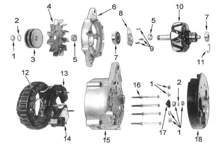
1 - nuts; 2 - washers; 3 - pulley; 4 - fan impeller; 5 - remote bushing; 6 - cover on the drive side; 7 - bearing; 8 - plate; 9 - screws; 10 - rotor; 11 - retaining ring; 12 - stator; 13 - diode assembly; 14 - regulator; 15 - cover from the side of the sliding rings; 16 - bolts; 17 - insulator; 18 - plastic cover
1. Remove the generator from the car.
2. Loosen the fixing screws and remove (if one is installed) plastic cover on the back of the generator.
3. Draw a line on the drive side cover, stator and slip ring side cover to mark the position of the components relative to each other.
4. Remove the through bolts securing the drive side cover to the slip ring side cover.
5. Using suitable levers, carefully pry the slip ring side cover assembly with stator off the drive side cover assembly with rotor. To avoid damage to the stator, do not push the levers too far.
Note. If the assembly of the cover on the side of the sliding rings with the stator does not lend itself, it makes sense to warm it up for 3-4 minutes in the area of the ledge for the installation of the bearing with a powerful (200 W) soldering iron.
6. Clamp the cover assembly on the drive side with the rotor in a vise with soft jaws and give the nut securing the drive pulley to the rotor.
7. Remove the pulley, fan impeller and rotor shaft spacer.
8. Using a soft-faced hammer, knock the rotor assembly out of the cover and remove the spacer from the rotor shaft.
9. If necessary, loosen the screws securing the bearing holder plate to the cover on the drive side and carefully remove the bearing from the cover.
10. If necessary, remove the sliding ring side bearing from the rotor shaft using a suitable puller.
11. Give nuts and remove a washer and an insulator from a cover from sliding rings.
12. Remove the cover from the stator assembly.
13. If necessary, unsolder the regulator diode assembly from the stator.
Note. Avoid overheating the contacts to avoid damage to the diode assembly and/or regulator. Clamp the wire with pliers as close as possible to the soldering point - the pliers will act as a heat sink.
4.2L EFI Models (since 1992 issue.)
4.2L EFI Model Generator Components
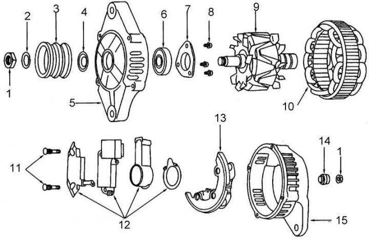
1 - nut; 2 - washer; 3 - pulley; 4 - shield; 5 - cover on the drive side; 6 - bearing; 7 - plate; 8 - screws; 9 - rotor; 10 - stator; 11 - studs; 12 - components of the brush holder and regulator; 13 - diode assembly; 14 - insulator; 15 - cover on the side of sliding rings
1. Remove the generator from the car.
2. Draw a line on the drive side cover, stator and slip ring side cover to mark the position of the components relative to each other.
3. Remove the through bolts securing the drive side cover to the slip ring side cover.
4. Carefully prying with suitable levers, remove the slip ring side cover assembly from the drive side with the rotor. To avoid damage to the stator, do not push the levers too far.
Note. If the assembly of the cover on the side of the sliding rings with the stator does not lend itself, it makes sense to warm it up for 3-4 minutes in the area of the ledge for the installation of the bearing with a powerful (200 W) soldering iron.
5. Clamp the drive side cover assembly with the rotor in a vise with soft jaws.
6. Give a nut of fastening of a driving pulley to a rotor and remove a pulley.
7. Using a soft-faced hammer, knock the rotor assembly out of the cover and remove the spacer from the rotor shaft.
8. If necessary, loosen the screws securing the bearing holder plate to the cover on the drive side and carefully remove the bearing from the cover.
9. If necessary, remove the slip ring side bearing from the rotor shaft using a suitable puller.
10. Give nuts and remove an insulator from a cover from a sliding rings. Remove the cover from the stator assembly.
11. If necessary, give the fixing screws and remove the rectifier, regulator and brush assembly from the stator.
Cleaning the components
1. To avoid damage to windings, do not immerse generator components in solvent.
2. End caps can be washed in kerosene or other cleaning liquid after removal from the unit. Then they should be dried thoroughly.
3. Compressed air can be used to remove dust from the stator and rotor windings.
4. Burnt or scratched slip rings can be polished with fine sandpaper.
5. Wipe the brushes and brush holders with a rag soaked in gasoline. Inspect the brush holders, remove burrs from them.
6. Check the bearings for signs of wear, free rotation and lubrication. Replace if necessary.
Attention! Checking the condition and correct functioning of the components
Note. All components subject to electrical checks should be installed on dielectric stands.
Assembly of the rotor with excitation windings
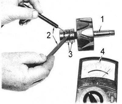
1. Checking the short circuit of the windings to ground is carried out using an ohmmeter. Connect one of the instrument's test leads to one of the field windings/slip rings and the other to one of the rotor pole pieces (see accompanying illustration).
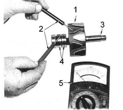
1 - pole tip; 2 - measuring probes; 3 - rotor; 4 - sliding rings; 5 - ohmmeter
2. If there is continuity and no apparent cause of the short circuit can be identified and repaired, replace the rotor assembly.
3. To check the resistance of the rotor windings, connect the test leads of an ohmmeter to the sliding rings (see accompanying illustration). If there is no continuity, replace the rotor.
1 - rotor; 2 - measuring probes; 3 - sliding rings; 4 - ohmmeter
4. The stator is checked using a probe lamp and an ohmmeter.
5. The stator wires must be disconnected from the rectifier assembly.
6. Connect one of the test probes of the ohmmeter to one of the stator wires, the second probe to the second wire. Read the instrument reading.
7. Repeat the measurement for the remaining wires, thus checking all phases.
8. If there is a difference between the measurement results, the stator assembly must be replaced.
9. Connect a jumper wire between the negative terminal of the charged 12-volt battery and the stator winding frame. Alternately connect one of the probe lamp wires to all stator wires.
10. Turning on the probe leg (dim glow) should be taken as a sign of a short circuit. The stator assembly must be replaced.
Diode assembly
Note. The diode assembly can be checked with an ohmmeter after removing it from the stator.
1. Connect the test leads of an ohmmeter between the case and one of the contacts of the diode assembly. Reverse the order in which the probes are connected and make sure that conduction occurs in only one direction.
2. Repeat the test for all other contacts in the assembly. If the test condition is not met (conduction on any of the contacts takes place in both directions, or is completely absent), replace the diode assembly.
Brushes and brush springs
1. Check the brush springs for signs of overheating and deformation. Check the free sliding of the brushes in the brush holders.
2. Measure the length of the brushes, compare the measurement result with the requirements tables of sizes and adjustments, if necessary, replace the brushes.
Assembly
Assembly is carried out in the reverse order of dismantling.
Carburetor models 4.2 l and 3.0 l
1. Install a new bearing in the drive side cover, secure it with the holder plate, tighten the mounting screws.
2. Install a new bearing on the rotor from the side of the sliding rings - press on the inner race. Make sure that the groove for installing the retaining ring does not fall under the sliding rings.
3. Install the circlip on the side of the bearing facing the sliding rings. Make sure that the protruding part of the ring is located in the deepest part of the groove.
4. Using a soldering iron and a pair of pliers (as a heat sink) solder the contacts of the diode assembly and the regulator to the stator assembly.
Note. To avoid damaging the diodes and/or the regulator, be careful not to overheat the contacts. Before soldering, make sure that the wires of the diode assembly are correctly placed.
5. Install the stator, rectifier and regulator assembly into the slip ring side of the cover and screw on the fixing nuts.
6. Install the cover, washer and nuts on the alternator BAT terminal.
7. Fix the brushes in a protruding position with a piece of wire (straightened paper clip), threaded into a special hole in the cover from the side of the sliding rings.
8. Clamp the rotor in a vise with soft jaws and put the cover on the side of the slip rings with the bearing assembly on its shaft.
Note. If necessary, warm up the cover for 3÷4 minutes in the bearing installation area with a powerful (200 W) soldering iron.
9. Place the drive side cover with bearing on the rotor shaft. Check that the spacer bushing is installed correctly.
10. Achieve the alignment of the marks of the relative position of the generator units, then screw in and firmly tighten the through bolts.
11. Slide the spacer sleeve, fan impeller, pulley and spring washer onto the rotor shaft, then screw on the nut and tighten it to the required torque.
12. Remove the wire (paperclip), used to hold the brushes in the protruding position and manually check the freedom of rotation of the rotor.
4.2L EFI Models (since 1992 issue.)
1. Install a new bearing in the drive side cover, secure it with the holder plate, tighten the mounting screws.
2. Install the new bearing on the slip ring side of the rotor (press on the inner race).
3. Install the rotor shaft into the drive side cover (check the correct installation of the distance sleeve).
4. Install a pulley on the rotor shaft and tighten its fastening nut with a force of 49÷64 Nm.
5. Clamp the drive side cover assembly with the rotor in a soft vise.
6. Fix the brushes in a protruding position with a piece of wire threaded through a special hole in the cover from the side of the sliding rings.
7. Place the drive end cover with bearing onto the rotor assembly. Achieve the alignment of the marks of the relative position of the generator nodes.
8. Screw in the through bolts and tighten them with a force of 3÷4 Nm, remove the wire (paperclip), used to lock the brushes in the protruding position, then manually check the free rotation of the rotor.