


Removing
1. Disconnect the negative cable from the battery.
2. Remove the distributor cover assembly with BB wires.
3. Disconnect from the distributor electroconducting and a vacuum hose of the corrector of ignition.
4. Turn the engine clockwise so that the slider turns with its nose towards the location of the first cylinder spark plug wire terminal. Make sure that the distribution marks on the engine are aligned.
5. Mark position of the case of the distributor in relation to a head of cylinders, then give a fixing bolt and remove the distributor. Try to remember in which direction the slider turned and fix its final position.
Installation
Installation is in the reverse order.
1. Check the condition of the O-ring (rings) distributor, replace the defective ones.
2. If the engine was cranked after the distributor was removed, by turning the crankshaft, bring the piston of the first cylinder to a position close to the TDC position of the end of the compression stroke, then achieve the alignment of the TDC mark of the crankshaft with the zero mark of the distribution scale on the timing cover.
Note. If you unscrew the spark plug of the first cylinder and clamp the spark plug hole with your finger, then when the piston approaches the TDC position of the end of the compression stroke, a distinct pressure sensation will appear.
3. If the engine did not turn, set the slider to its original position (which he occupied after being removed from the engine) and install the distributor in the cylinder head, achieving the alignment of the landing marks. Screw in the mounting bolt.
4. Connect to the distributor electroconducting and a vacuum hose and execute installation of an angle of an advancing of ignition.
Disassembly
Models 3.0 l
1. Loosen the fixing screw and remove the slider. Remove the rev limiter screen and o-rings (see accompanying illustration).
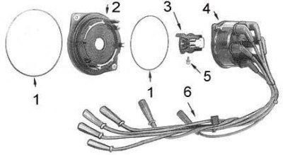
1 - sealing ring; 2 - screen for switching the speed limiter; 3 - slider; 4 - cover; 5 - screw; 6 - wires
2. Disconnect the electrical wiring from the control unit. Give fixing screws and take a plait of wires from the distributor.
3. Loosen the fixing screws and remove the stator and magnet (the internal components of the distributor are shown in the accompanying illustration).
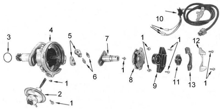
1 - screws; 2 - vacuum ignition timing corrector; 3 - sealing ring; 4 - body; 5 - weights; 6 - springs; 7 - rotor shaft of the ignition sensor; 8 - base plate; 9 - control unit; 10 - electrical wiring; 11 - ignition sensor rotor; 12 - stator; 13 - magnet
4. Using two screwdrivers, remove the ignition sensor rotor from the shaft, remove the cylindrical pin. Note the installation position of the rotor.
5. Give the remained screws of fastening of the block of the vacuum corrector. Remove the E-clip and remove the block from the distributor.
6. Loosen the fixing screws and remove the base plate from the distributor.
7. Supporting the drive gear of the distributor, give the screw securing the rotor shaft of the ignition sensor. Remove the shaft from the distributor housing.
8. Mark the mounting positions of the springs and weights of the ignition timing corrector.
9. Disconnect and remove springs.
10. Remove the E-clamps and remove the corrector weights.
Models 4.2 l
Distributor components
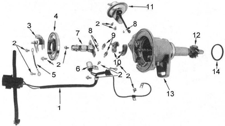
1 - wiring harness; 2 - screws; 3 - breaker contacts; 4 - base plate; 5 - wire; 6 - capacitor; 7 - cam; 8 - E-shaped clamps; 9 - springs; 10 - weights; 11 - vacuum corrector block; 12 - gear; 13 - body; 14 - sealing ring
1. Give fixing screws and remove the slider from the distributor shaft. Remove the rev limiter shift screen and o-rings.
2. Give fixing screws and remove a plait of wires from the distributor.
3. Give the remaining fasteners and remove the breaker contact assembly from the distributor.
4. Give fixing screws and remove a ground wire from the distributor.
5. Give the remained screws of fastening of the block of the vacuum corrector. Remove the E-clamp and remove the vacuum corrector from the distributor.
6. Loosen the fixing screws and remove the base plate from the distributor.
7. While supporting the drive gear, loosen the cam screw. Remove the cam from the distributor housing.
8. Mark the mounting positions of the springs and weights of the ignition timing corrector.
9. Disconnect and remove springs.
10. Remove the E-clamps and remove the corrector weights.
Cleaning and checking the condition
1. Thoroughly wash all components, with the exception of the electrical components and the vacuum ignition timing corrector, in a suitable solvent.
2. Assess the degree of wear of the lower shaft and distributor housing. Replace if necessary.
3. Check the cam, weights and springs for signs of wear and damage. Replace if necessary.
4. Check the base plate for wear and damage. Replace if necessary.
5. On 4.2L models, check the breaker contacts for signs of wear and cavities. Replace if necessary.
Note. When installing a new breaker contact assembly, be sure to also replace the capacitor.
6. Check the distributor cap, slider and rev limiter screen for cracks, carbon tracks, burnouts and corrosion on the terminals.
7. Assess the degree of wear of the central coal. Measure its protrusion.
8. Check the vacuum corrector unit for signs of diaphragm leakage by pressing down on the connecting rod, press your finger against the suction tube, then release the rod. The vacuum under the finger must be held for at least 30 seconds.
9. Check up a condition of sealing rings, replace defective.
10. Assess the degree of wear of the drive gear.
Assembly
Models 3.0 l
Assembly is carried out in the reverse order of dismantling.
1. Moderately lubricate with high temperature grease the shafts of the weights, springs and rods of the vacuum ignition corrector.
2. Install the weights and springs in accordance with the marks made during the dismantling process. Secure them with E-clamps.
3. Establish a shaft of a rotor of the gauge of ignition, screw in the fixing screw.
4. Install the base plate, fix it with screws.
5. Install the ignition timing vacuum corrector and E-clamp.
6. Install the wiring harness, fix it with screws. Screw in the fixing screws of the vacuum corrector block.
7. Adjust the air gap.
8. Install the rev limiter screen and o-rings.
9. Install the slider, fix it with a screw.
10. Install the distributor on the engine.
Models 4.2 l
1. Moderately lubricate with high temperature grease the shafts of the weights, springs and rods of the vacuum ignition corrector.
2. Install the weights and springs in accordance with the marks made during the dismantling process. Secure them with E-clamps.
3. Mount the cam and secure it with the screw.
4. Install the base plate, do not screw in the fixing screws at this stage.
5. Install the ignition timing vacuum corrector and E-clip.
6. Install the ground wire and screw in the base plate screws.
7. Install the breaker contact assembly and secure it with screws.
8. Install the wiring harness, fix it with screws. Screw in the fixing screws of the vacuum corrector unit.
9. Adjust the gap in the breaker contacts.
10. Install the rev limiter screen and o-rings.
11. Install the slider, secure it with a screw.
12. Install the distributor on the engine.