


Design of ignition distributor with contact breaker
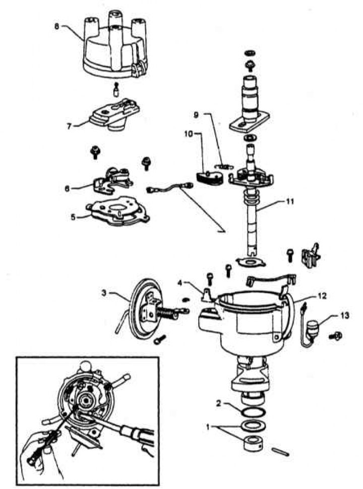
1 - Retainer; 2 - sealing ring; 3 - Vacuum corrector diaphragm; 4 - Grounding; 5 - Breaker plate; 6 - Movable contact holder; 7 - Runner; 8 - Lid; 9 - Centrifugal regulator spring; 10 - Centrifugal governor weights; 11 - Shaft; 12 - Body; 13 - Capacitor
Design of the distributor of the transistor ignition system
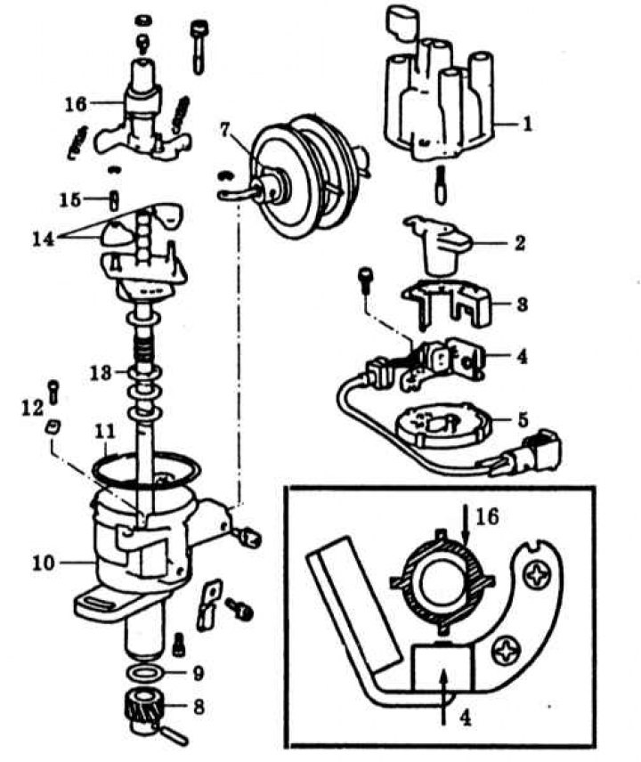
1 - Lid; 2 - Runner; 3 - Dust shield; 4 - Signal generator; 5 - Breaker plate; 6 - Vacuum corrector diaphragm; 7 - Gasket; 8 - Drive gear; 9 - Sealing ring; 10 - Body; 11 - Sealing ring; 12 - Thrust bearing; 13 - Regulator shaft; 14 - Weights; 15 - Bearing; 16 - Signal rotor
Checking and adjusting
Distributor with contact breaker
1. The design of the distributor with a contact breaker is shown in the accompanying illustration.
2. Before adjustment, it is necessary to check the condition of the contacts. In case of minor burning, the contacts should be cleaned with fine-grained sandpaper; in case of detecting noticeable defects, they should be replaced.
3. Clean the contacts using a diamond file of slight thickness. Try to achieve absolute parallelism of the mating surfaces. The convexity of one contact should be completely eliminated, without selecting the depression on the other. After cleaning, wipe the contacts with a rag soaked in gasoline.
4. The main causes of severe contact burning include a capacitor malfunction, loosening of the fixed contact or the breaker grounding lead. Be sure to check the quality of the grounding contacts to the engine mass.
5. Rotate the crankshaft so that the contacts are fully aligned and measure the gap between them. Compare the measurement result with the requirements of the Specifications, if necessary, loosen the fastening screw and, by moving the contact with a screwdriver, achieve the required value.
6. Tighten the screw and repeat the check.
7 Now it is necessary to check the duration of the closed state of the contacts (by crankshaft rotation angle). Prepare a special measuring device between the negative terminal of the ignition coil and the ground. Start the engine and warm it up to normal operating temperature. Adjust the idle speed.
8. Disconnect the vacuum hose from the vacuum regulator assembly and measure the angle of the breaker contacts in the closed state. The required value is 52° (by crankshaft rotation angle). If necessary, make the appropriate adjustments by adjusting the gap between the contacts.
9. To decrease the angle, increase the gap; to increase it, decrease it. For different models, the required value of the angle of the closed state of the breaker contacts may vary from the range of 49°÷55°.
10. A capacitor is connected in parallel to the contact breaker, which together with the primary winding of the ignition coil forms an oscillatory circuit. At the moment of opening the circuit, the capacitor is charged by the self-induction current of the primary winding, which contributes to an increase in the rate of decrease of the magnetic flux, i.e. an increase in the voltage in the secondary winding. The absorption of the self-induction current at the moment of breaking the circuit reduces sparking between the contacts of the breaker, as a result of which the reliability of the system increases significantly.
11. Capacitor breakdowns lead to ignition failure and disruption of the low-voltage circuit. Signs of capacitor failure are interruptions in engine operation and significant burning of the breaker contacts.
12. To check the capacitor, you should measure its capacity, but you can also use a regular tester, switching it to the high-resistance measurement mode. If the device arrow deflects sharply and then smoothly returns to its original position, then the capacitor is functioning properly. A zero or constantly decreasing reading indicates the need to replace the capacitor
13. There is another simple way to check the condition of the capacitor: with the ignition on, manually open the breaker contacts - if a spark is formed, then the capacitor is damaged.
14. Do not leave the ignition on for a long time with the engine off. If the breaker contacts are closed when the ignition is turned on (the probability of such a situation is quite high), as a result of strong heating by the flowing current, the breaker hammer spring may be released and lose its elasticity. At high speeds, the spring ceases to ensure the sharpness of the contact closure with the required frequency. As a result, interruptions in engine operation occur, which is usually accompanied by pops in the exhaust system.
15. Insufficient gap size in the breaker contacts manifests itself in interruptions in engine operation in deceleration mode. In the same way, the loosening of the distributor fastening, the contact connectors of the low-voltage circuit, and also the contact in the ignition switch manifests itself).
16. A decrease in the gap size in the contacts by 0.01 mm corresponds to a change (increase) duration of the closed state of contacts per 1 degree.
17. Increasing the gap in the breaker contacts leads to a disruption in the stability of high engine speeds.
Distributor of transistor ignition system
1. The design of the distributor of the transistor ignition system is shown in the illustration.
2. As part of routine maintenance of the distributor, periodically check and adjust the signal generator air gap.
3. Remove the distributor cap and rotor. Turn the crankshaft so that the signal rotor tooth aligns with the signal generator protrusion and measure the gap between them using a blade-type feeler gauge. The nominal range is 0.2÷0.4 mm.
4. To adjust the gap, loosen the two fixing screws and turn the signal generator to the appropriate side, then tighten the screws.
5. Before installing the runner and cover, also check the condition of the cover segments and the central electrode. Replace if necessary.
6. To disassemble the distributor, remove it from the vehicle. Remove the runner and plastic dust shield. Remove the sealing ring from the housing rim. Remove the two retaining screws and remove the signal generator assembly with the wiring.
7. Remove the mounting screw, release the lock and lever, and remove the vacuum regulator assembly.
8. Remove the two mounting screws and remove the breaker plate.
9. Mark the installation position of the regulator springs and remove them from the assembly.
10. Remove the oil deflector from the top of the rotor, unscrew the mounting screw and remove the signal rotor.
11. Mark the installation position of the snap rings and centrifugal governor weights, remove the components.
12. Clean the components and check their condition. Replace any defective parts.
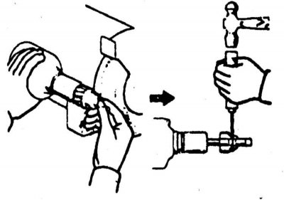
13. If the distributor shaft drive gear is significantly worn, file or cut off the riveted end of the locking pin, then secure the assembly and knock out the pin.
14. Assembly is carried out in the reverse order. When installing the shaft with the gear, align the holes of the bearing holder and the housing, install the shaft and screw in two fastening screws.
15. Align the pin holes in the gear and shaft. Hammer in a new pin and rivet its ends. Make sure the marks on the gear and signal rotor align.
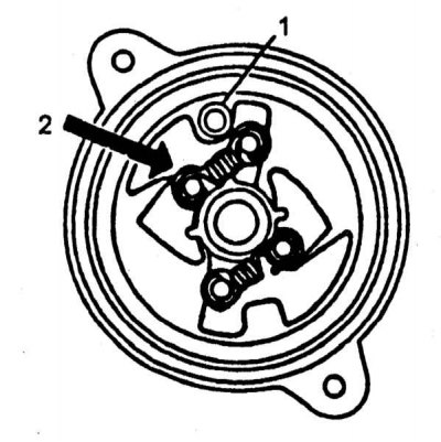
16. Lightly lubricate the governor shaft with clean engine oil, install it on the signal rotor and align the mark with the locking pin.
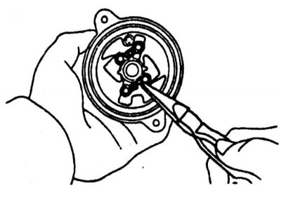
17. Install the weights with bearings, secure the components with retaining rings.
Note: The weights must be installed strictly in their original places. Install the centrifugal regulator springs in their original places.
18. Screw in and tighten the signal rotor mounting screw. Pack the recess with grease, install the oil deflector (plug). Install the interrupter plate. Install the vacuum interrupter assembly.
19. Install the signal generator, screw in the mounting screws, but do not tighten them all the way. Align the signal rotor tooth with the generator projection, adjust the gap size, then tighten the screws completely.
20. Install the dust shield, O-ring and distributor rotor. Install the distributor to the engine.
Note: The sealing ring must fit into the receiving recess on the end of the distributor.
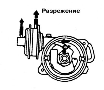
21. Check the proper functioning of the vacuum corrector by creating a vacuum at the input of its diaphragm using a hand vacuum pump - the regulator lever should move when the vacuum depth changes.
Removal
1. Disconnect the negative cable from the battery.
(The source of the article is on the website nissanbook.ru)
Warning! If the car stereo system is equipped with a security code, make sure you have the correct combination to activate the audio system before disconnecting the battery!
2. If equipped, remove the protective screen from the distributor cap. Note that the spark plug wire connection terminal for the first cylinder on the distributor cap is marked with a protruding digital mark in the form of a 1.
Note: Some distributors may not have this mark.
3. Disconnect the main electrical connector and ground contact connector from the distributor.
4. Remove the distributor cap (see Chapter Settings and ongoing maintenance). Turn the engine by the crankshaft pulley bolt so that the distributor rotor turns towards the position of the spark plug wire terminal of the first cylinder on the cover (see section Bringing the piston of the first cylinder to the top dead center (TDC) position).
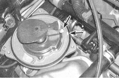
5. Mark the runner nose position on the distributor housing rim. Also mark the position of the distributor housing base relative to the cylinder head surface.
 |
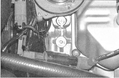 |
6. Loosen the clamping mounting bolt and remove the distributor assembly from the cylinder head.
Caution! Try not to allow the engine to turn with the distributor removed, as this will make the markings applied during the dismantling process meaningless.
Installation
1. Install the distributor in its regular place in the cylinder head. Make sure that the mounting marks applied during dismantling are aligned.
2. To engage the camshaft and distributor shaft drive gears, you may have to rotate the assembly housing slightly. Make sure the distributor is seated completely in the head. Check again that the seat marks are aligned correctly.
Note: If the crankshaft was turned with the distributor removed, the engine should be returned to the TDC position of the end of the compression stroke (see section Bringing the piston of the first cylinder to the top dead center (TDC) position).
3. Loosely screw in the distributor mounting clamp bolt.
4. Install the distributor cap and tighten the screws securely.
5. Connect the electrical wiring to the distributor.
6. If removed, connect the high voltage wires to their corresponding ignition leads.
7. Connect the negative cable to the battery.
8. Check the correct setting of the ignition timing angle, if necessary, make the appropriate adjustments (see section Checking and adjusting ignition timing settings), then tighten the distributor mounting clamp bolt completely. If equipped, install the distributor cover protective screen.