Attention! Due to the very high voltage generated in the ignition system, the maintenance of its components must be carried out with extreme care. This note applies not only to the main components of the electronic ignition system, but also to all related components, including spark plug wire tips, tachometer and other diagnostic equipment.
You should not immediately attribute the cause of the failure when starting the engine to a malfunction in the functioning of the ignition system. Before doing the following checks:
- a) Check the condition of the battery wire lugs and the reliability of their attachment to the pole terminals;
- b) Check Battery Status (see Section Checking the condition and replacing the battery), if necessary, replace it with a known good one;
- c) Visually assess the condition of the distributor and ignition coil connectors (models until 1995 issue.);
- d) Check the condition of the fuses in the fuse box installed in the passenger compartment (see chapter Onboard electrical equipment). In case of detection "breakdown" find out and eliminate the cause of the overload.
Models 1993 and 1994 issue
1. If the engine cranks but does not start, disconnect the wires from the spark plugs and connect them to a special calibrated ignition tester (ask at car accessories stores). Connect the meter's terminal to a bolt or metal bracket on the power unit, then turn the engine over - a clearly visible spark of bright blue color should jump between the electrode and the tester body (weak spark intensity should be considered as its absence).
2. If sparking occurs properly, therefore, the required BB voltage is applied to the corresponding spark plug. After repeating the test for the remaining candle wires, make sure that the condition of the cover and the distributor slider is in good condition. The next step in the test will be to determine the condition of the spark plugs themselves - unscrew them from the cylinder head and refer to the material in the relevant Section of the Chapter Settings and ongoing maintenance.
3. In the absence of sparking, or its excessively weak intensity, check the distributor cover and slider, as well as the connecting BB wires for signs of oxidation and mechanical damage (see chapter Settings and ongoing maintenance). If traces of moisture are found, wipe the ignition system components and recheck.
4. If no violations can be detected during the inspection of the distributor and electrical wiring, disconnect the central BB wire (from the coil) from the ignition distributor cover and connect it to a universal meter (spark plug wires should be connected to spark plugs), then recheck. If sparking occurs this time, replace the distributor cap and runner (the possibility of damage to the explosive electrical wiring is also not excluded).
5. If there is still no spark, remove the BB wire going from the coil to the distributor and check the condition of its contact terminals. Using an ohmmeter, check the wire for signs of an open. It would be wise to replace the wire with a known good one at the time of further testing.
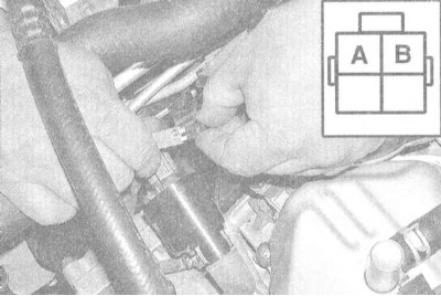
6. If replacing the wire does not restore the correct sparking, check the correctness of the voltage supply to the coil from the ignition switch when the key is turned to the ON position (do not start the engine). Connect a 12 volt test light to the negative battery terminal or a good ground on the engine block. Disconnect the electrical wiring from the coil and check for battery voltage at the white-green wire terminal of the connector. If there is no voltage, check the condition of the wiring in the section of the circuit between the coil and the ignition switch.
Note. For more information on color coding of wires, see Chapter Onboard electrical equipment.
7. If the coil is powered properly, connect the test lamp on the LED to the positive terminal of the battery. Connect the lamp contact probe to the light green wire terminal in the coil wiring connector, then turn the engine with the starter - the lamp should flash when the engine is cranked. This check allows you to make sure that the trigger signal is received correctly (ground signal) from PCM and power transistor. If the trigger signal is present, then the PCM, camshaft position sensor and power transistor are functioning properly.
Attention! To avoid the risk of failure of the PCM, use only an LED test lamp during this test!
8. If there are signs of a trigger signal failure, check the condition of the RC assembly and the power transistor (see Section Checking the condition and replacing the power transistor (1993 and 1994 models issue)).
Note. The RC assembly connector is duct-taped to the wiring harness directly to the left of the ignition distributor. If the transistor and resistor are OK, proceed to check the camshaft position sensor (see chapter Engine management systems).
9. If the supply voltage and trigger signal are properly supplied, the absence of sparking can be explained by internal malfunctions in the ignition coil - measure the resistance of its primary and secondary windings (see Section Check of a condition and replacement of coils of ignition). If there are signs of breakage, replace the coil.
10. If the performed checks confirm the correct operation and condition of all the components listed above, you should drive the car to a service station for PCM diagnostics.
Models since 1995 vol.
1. If the engine cranks but does not start, verify that the battery voltage is being supplied to the spark plugs. Remove coil (see Section Check of a condition and replacement of coils of ignition) and connect a calibrated ignition tester to the spark plug tip (do not forget to connect the wiring to the coil), ground the tester to the mass of the power unit. Turn the engine over - a bright blue spark of good intensity should jump between the tester electrode and its body.
2. If sparking occurs properly, therefore, the required BB voltage is applied to the corresponding spark plug (proceeding in a similar manner, check each of the candles in turn). The next step in the test will be to determine the condition of the spark plugs themselves - unscrew them from the cylinder head and refer to the material in the relevant Section of the Chapter Settings and ongoing maintenance.
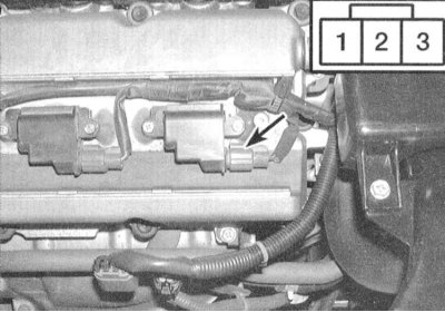
3. In the absence of sparking, or its excessively weak intensity, remove the candle tip and check the condition of its contact terminals. Using an ohmmeter, check the tip for signs of a break. Make sure that the battery voltage is supplied to the coil from the ignition switch (key in ON position, engine not running). Connect a 12 V test lamp to the negative terminal of the battery or engine ground and make sure that the power to terminal No. 1 of the coil connector is good (red wire). If there is no battery voltage, check the condition of the wiring between the coil, the ECCS relay and the ignition switch. Also check for proper grounding (see chapter Onboard electrical equipment).
4. If there is battery voltage on the coil, connect the test lamp on the LED to the positive terminal of the battery and test the terminal No. 3 of the connector - the lamp should flash when the engine is cranked. This check allows you to make sure that the trigger signal is received correctly (ground signal) from PCM and power transistor. If the trigger signal is present, then the PCM and shaft position sensors are functioning properly.
Attention! To avoid the risk of failure of the PCM, use only an LED test lamp during this test!
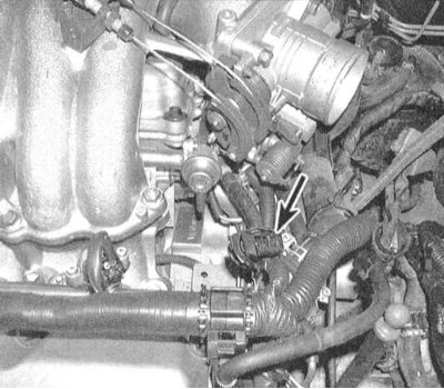
5. If there are signs of a trigger signal failure, check the condition of the capacitive assembly.
Note. The capacitive assembly connector is taped to the wiring harness directly on the transmission case. If the capacitor is OK, proceed to check the crankshaft and camshaft position sensors (see chapter Engine management systems).
6. If the supply voltage and trigger signal are properly supplied, the absence of sparking can be explained by internal problems in the ignition coil (see Section Check of a condition and replacement of coils of ignition). If there are signs of a problem, replace the coil.
7. If the checks performed confirm the correct functioning and condition of all the components listed above, you should drive the car to a service station for PCM diagnostics.