


- a) Check the condition of the battery wires where they are connected to the battery terminals. Check the reliability of the terminal clamps;
- b) Check the battery status (see section Checking the battery status and replacing it). If necessary, recharge the latter or replace it with a new one;
- c) Check the condition of the wiring and electrical connections of the generator and voltage regulator;
- d) Check the condition and tension of the alternator drive belt (see Chapter Settings and ongoing maintenance). Replace if necessary;
- e) Check the generator mounting bolts for tightness;
- f) Start the engine and evaluate the intensity of the background noise emitted by the generator;
- g) If equipped, check the condition of the fuse links in the fuse box in the engine compartment of the vehicle (see Chapter On-board electrical equipment).If any of the inserts fail, investigate and eliminate the causes of the overload;
- h) Check the proper functioning of the charge indicator lamp in the engine instrument panel. With the ignition on and the engine not running, the lamp should light. Otherwise, check the condition of the circuit between the generator and the indicator lamp;
- i) Check the condition of all fuses connected in series to the charging system circuit. The location of fuses and fuse links may vary depending on the year of manufacture and model configuration, however, the designations remain the same. See the electrical connection diagrams at the end of the Chapter On-board electrical equipment.
2. Using a voltmeter, measure the voltage produced by the battery on the rear side of the generator with the engine off and all electrical consumers disconnected (heater fan, radio, cigarette lighter, cooling system fan, etc., etc.). The measurement result should be around 12 V, or slightly higher if the engine has been running for the last hour.
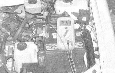
3. Start the engine and check the battery output voltage again. This time the reading should be around 15V (but not higher).
4. Turn on the headlights - the voltage should drop slightly, but not below the value recorded during the measurement described in paragraph 2.
5. If the charging voltage exceeds 15 V, then there is a failure of the voltage regulator and the generator must be replaced (see section Removal and installation the generator).
6. When the charging voltage is too low (less than 12 V) the generator should be checked for proper functioning (see below).
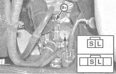
7. Using a voltmeter, probe the "B" terminal on the rear of the generator connector. The desired reading is 12 V with the ignition off.
8. Turn on the ignition (do not start the engine) and probe each terminal in turn. There should be a voltage of 12 V on terminal "S", (1.5÷2.0) V on terminal "L", and 12 V on terminal "B".
9. Start the engine, increase its speed to 2000 rpm and repeat the check. This time the following picture should take place: "S" and "B" - (14.0÷14.7) V, "L" - (13.0÷14.0) V.
Caution! Make sure that measuring wiring, hair and clothing do not come into contact with moving parts in the engine compartment of the vehicle!
10. If the above checks are negative, evaluate the condition of the wiring of the corresponding circuit. If there are harness defects, replace the generator.
11. If you suspect that leakage currents are developing, leading to battery discharge, refer to the material in Section Checking the battery status and replacing it.
12. If signs confirming the presence of leakage current are detected, begin to carefully remove one by one the fuses of the main on-board power consumers, such as the radio, heater fan, luggage compartment lighting, etc. Continue removing the fuses until the test lamp goes out, then check the condition of the circuit of the corresponding consumer and make the necessary repairs. Repeat the check of the charging system condition.
13. If removing the fuses does not give any results, disconnect the output wire and other electrical wiring from the rear wall of the generator - the test lamp will turn off, indicating that the generator or voltage regulator is faulty - replace the assembly.