Models 4.2 l
1. Wash all components in solvent and dry with compressed air.
2. Assess the degree of wear of the components. Check them for damage and deformation, paying special attention to the condition of the shafts and gears.
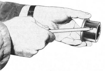
3. Check bearings and couplings for signs of wear, cracks and cavities (see accompanying illustration), evaluate how freely the bearings rotate.
Note. If the bearing is equipped with a cage and its condition cannot be visually determined, thoroughly wash the bearing in solvent, lightly oil it and rotate it slowly by hand, checking for jerks and pinching points.
4. Label all components of the assembly of each synchronizer. Slowly remove the synchronizer sleeve from the hub, remembering the installation position of the sliding keys and springs. The sliding keys are spring loaded - make sure they do not pop out when the clutch is removed. Stack the components of each assembly separately so that there is no confusion during assembly.
Note. To remove the sliding keys and the rear spring from the hub of the reverse gear synchronizer, first remove the holder plate with a puller and give two bolts, first plugging the center of the hub with a plug.
5. Check the synchronizer hubs and clutches for signs of wear and damage, paying special attention to the condition of the splines and slots for sliding keys (the components of the fifth gear synchronizer assembly are shown in the accompanying illustration).
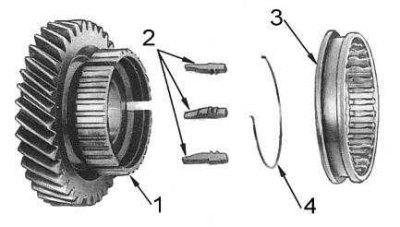
1 - gear; 2 - sliding keys; 3 - clutch; 4 - spring
6. Assess the condition of the sliding keys. Check the springs for signs of damage, deformation and loss of force being developed.
7. Check the synchronizer rings for cracks and signs of deformation. Slide the rings onto the respective gears until fully seated and use a blade-type feeler gauge to measure the gaps between the rings and gears (see accompanying illustration). If the gaps exceed the allowable values, replace the corresponding rings.
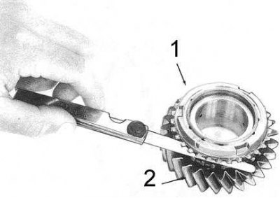
1 - gear
2 - synchronizer
8. Check the condition of the top cover components, paying special attention to the shift rods and forks. Replace worn, deformed and damaged parts.
9. Examine casings of a cover, the selector and management of the lever of a gear change on presence of deterioration signs and damages.
10. Check transmission case, extension housing and clutch dome for cracks or other damage.
11. Replace non-repairable components.
Note. It makes sense to restore the threads in the holes of aluminum cases. This work is best entrusted to service station specialists.
Note. If the transmission is dismantled for overhaul, it is advisable to replace the bearings. All circlips and roll pins must be replaced without fail. Retaining rings are available in various thicknesses. Measure the required thickness of the rings as they are removed from the transmission components.
Models 3.0 l
1. Wash all components in solvent and dry with compressed air.
2. Assess the degree of wear of the components. Check them for damage and deformation, paying special attention to the condition of the shafts and gears.
3. Check the condition and freedom of rotation of the bearings.
4. Label all components of the assembly of each synchronizer. Slowly remove the synchronizer sleeve from the hub, remembering the installation position of the sliding keys and springs. The sliding keys are spring loaded - make sure they do not pop out when the clutch is removed. Stack the components of each assembly separately so that there is no confusion during assembly.
5. Check the synchronizer hubs and couplings for signs of wear and damage, paying special attention to the condition of the splines and slots for sliding keys.
6. Assess the condition of the sliding keys. Check the springs for signs of damage, deformation and loss of force being developed.
7. Check the synchronizer rings for cracks and signs of deformation. Put on all the rings one by one (with the exception of the reverse gear synchronizer blocking ring) on the corresponding gears until fully seated and using a blade-type feeler gauge, measure the gaps between the rings and gears. If the gaps exceed the allowable values, replace the corresponding rings.
8. Lay the reverse gear cone on a flat surface and press the synchronizer ring against it. Using a dial gauge, determine the distance between the back of the cone and the blocking ring. If the measurement result is greater than 0.7 mm, replace the ring.
9. Assess the condition of the shift rods and forks. Also check the striker arm and retainer for signs of wear and damage.
10. Inspect carrier plate, clutch dome and extension housing for cracks or other damage.
11. Replace non-repairable components.
Note. All retaining and sealing rings, as well as cylindrical pins, must be replaced without fail. Remember that retaining rings differ from each other in thickness - measure them when removing. The compilers of this manual also recommend replacing bearings and seals.