Note. To lubricate components, use a lithium-based multipurpose grease unless otherwise specified in the procedure.
1. Lubricate all components with the recommended grade of grease before assembly.

2. Assemble the 1/2 gear synchronizer assembly in accordance with the marks made during the dismantling process. Make sure that the sliding keys are correctly aligned with the three V-grooves in the splines of the coupling. Spring locks should not be opposite (see accompanying illustration).
3. Assemble the 3/4 gear synchronizer assembly (with labels). Track alignment of keys with flutes. Install springs (locks in different directions). The hooks at the ends of the springs must fit into the corresponding hole in the synchronizer hub.
4. Taking into account the labels, assemble the reverse gear synchronizer assembly. Make sure that the clutch is facing the narrow end of the rear side of the hub, and the locks of the springs are facing in different directions. Using a mandrel, press the holder plate onto the hub flush with the end surface of the latter.
5. Install the blocking ring, reverse gear and roller bearing on the reverse synchronizer assembly (observe the installation direction of the parts). Place the assembly in a press, supporting the synchronizer hub with support plates and install the driven shaft.
6. Install the driven shaft in the press, supporting the reverse gear with support plates, and put the first gear, bearing and synchronizer ring on the shaft.
Note. The 1st and 2nd gear lock rings are not interchangeable. The first gear ring is distinguished by the presence of three gaps in the teeth (see accompanying illustration).
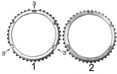
1 - 1st gear synchronizer blocking ring
2 - 2nd gear synchronizer blocking ring
3 - pass
7. Put the hub of the 1/2 gear synchronizer on the driven shaft (use a press and a suitable mandrel). Make sure that the grooves in the surface of the hub are facing away from the first gear (see accompanying illustration).
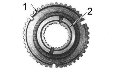
1 - hub
2 - groove
8. Measure the side clearance between the circlip and the synchronizer hub. Compare measurement result with regulatory requirements (see tables of sizes and adjustments at the end of the guide). Pick up a new retaining ring of the required thickness.
9. Fit the second gear synchronizer ring and the second gear to the driven shaft. Install the 3rd Gear Bearing Clutch (use a press and a suitable mandrel). Make sure the clutch flange is facing the 2nd gear.
10. Put the bearing, third gear and synchronizer blocking ring on the driven shaft. Install the shaft in the press, supporting its end with support plates.
11. Press the 3/4 gear synchronizer assembly onto the shaft. Make sure the oil grooves in the hub are facing the 3rd gear.
13. Check end play.
12. Measure the backlash between the retaining ring and the synchronizer hub (see accompanying illustration). Compare result with data tables of sizes and adjustments and select a new ring of the required thickness.
14. Put the bearing on the input shaft, making sure that the groove for the retaining ring in the outer race is turned away from the input shaft gear, then, supporting the bearing with support plates, press the shaft into it.
15. Put the spacer sleeve on the input shaft and measure the backlash between the retaining ring and the sleeve. Compare measurement result with regulatory requirements (see size and adjustment tables at the end of the manual), select a new retaining ring of the required thickness.
16. Install the toothed ring holder on the intermediate shaft and measure the backlash between the snap ring and the holder. Pick up a new ring of the required thickness. Remove the holder from the intermediate shaft.
17. Lubricate the steel ball with grease and install the ball, toothed ring, belleville spring and holder on the front of the intermediate shaft. Make sure that the concave side of the spring is facing the toothed ring.
18. Install a new snap ring of the required thickness on the intermediate shaft so that it is pressed against the holder. Use a suitable mandrel and press the retaining ring onto the intermediate one until it is seated in the groove. Remove the mandrel and check that the ring fits correctly.
19. Press the inner races of the front and rear bearings onto the intermediate shaft (use a suitable mandrel). Install the narrow clip back.
20. Install the reverse idle gear with thrust washers into the transmission case. Make sure the tabs of the washers are in the grooves and the stepped side of the gear is facing forward (as before disassembly). Install the reverse intermediate shaft and locking tab. Tighten the fixing bolt to the required torque. The reverse intermediate shaft components are shown in the accompanying illustration.

1 - bolt; 2 - locking plate; 3 - shaft; 4 - thrust washer; 5 - bearings; 6 - gear
21. Install the intermediate and driven shafts in the transmission case. Turn the intermediate shaft so that its combined segment and the teeth of the ring are against the driven shaft.
22. Install the synchronizer ring and the output shaft guide bearing (use grease), then while holding the shaft, align the flat segment of the mainshaft synchronizer gear with the top cover hole, then install the mainshaft with a soft-faced hammer.
23. Center the intermediate shaft and use a soft-faced hammer to install the front bearing outer race. Make sure that the bearing is turned with the flared part of the roller cage towards the intermediate shaft.
24. Support the intermediate shaft and install the rear bearing outer race (use a soft-faced hammer again).
25. Hold a piece of hard board against the front of the countershaft and rotate the transmission so the board rests on a hard support. Put on a greased thrust washer (chamfer back on the shaft), then fit the reverse gear bearing sleeve onto the countershaft using a suitable drift. Make sure that the thrust washer is not caught between the coupling and the bearing cage.
26. Lubricate the lips of the new oil seal and install it in the front cover. Using a new gasket, install the front cover on the transmission and tighten the cover bolts to the required torque.
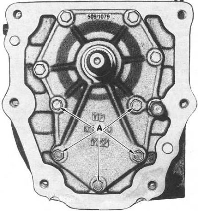
Note. Manufacturers insist that in those shown in the accompanying illustration (A) point, new bolts with locking coating were installed, however, old bolts can also be used by lubricating their threads with Loctite 242 sealant (or its equivalent).
27. Install the clutch dome, release lever and release bearing. Tighten the fixing bolts to the required torque.
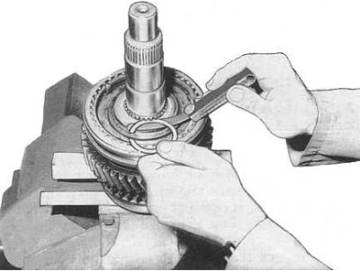
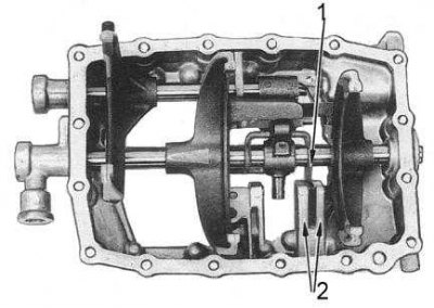
28. Slightly pull the output shaft out of the rear of the transmission and thread a suitable length of board ahead of the 2nd gear (see accompanying illustration), to prevent the transfer of load to the input shaft when dressed on the driven bearings and fifth gear gears.
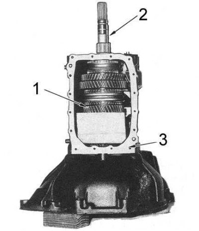
1 - 2nd gear gear
2 - driven shaft
3 - crankcase
29. Install the transmission vertically, resting the clutch dome on wooden blocks.
30. Remove the retaining ring from the output shaft bearing and, using a suitable mandrel, fit the bearing and fifth gear onto the shaft (the components of the rear of the driven shaft are shown in the accompanying illustration). Make sure that the bearing is installed with the groove for installing the retaining ring back. The protruding part of the gear should rest against the bearing. Install the circlip on the bearing.
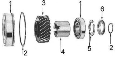
1 - bearing; 2 - retaining ring; 3 - gear wheel of the 5th gear; 4 - remote bushing; 5 - C-shaped retaining half rings; 6 - holder
31. Using a suitable mandrel, install the spacer bushing and rear bearing onto the driven shaft. Make sure that the sleeve is turned in grooves to the fifth gear, remove the piece of board from the transmission.
32. Measure the side clearance between one of the C-rings and the bearing. Compare the result with regulatory requirements. Pick up two half rings of the required thickness and install the holder and a new retaining ring on the driven shaft.
33. Install the bearing holder and pre-tighten the countersunk bolts to temporarily secure the holder. Tighten all fixing bolts to the required torque. Use a center punch to score the countersunk head of each of the bolts at two points.
34. Put the synchronizer clutch on the gear of the fifth gear of the intermediate shaft (flat side to gear). The narrow risks drawn on the inside of the coupling should be aligned with the grooves of the sliding keys.
35. Install sliding keys and springs. The long ends of the keys and the hooks of the springs must face the gear, and the springs must properly engage with the keys. To prevent the slip keys and their springs from jumping out, install a synchronizer ring on the fifth gear assembly.
36. Install the intermediate shaft fifth gear and the shift fork with the rod, making sure that the end of the rod equipped with a retaining ring is turned towards the transmission housing. Using a suitable mandrel, seat the synchronizer cone on the intermediate shaft.
37. Establish a washer on an intermediate shaft and measure a backlash between a lock ring and a washer. Compare the result with regulatory requirements (see tables of sizes and adjustments at the end of the guide) and select a new ring of the required thickness.
38. Check the axial play of the fifth gear of the intermediate shaft.
39. Lubricate the lips of the new oil seal and, using a suitable mandrel, fit the oil seal into the transmission extension housing.
40. After replacing the gasket, install the extension housing on the transmission and tighten the mounting bolts to the required torque.
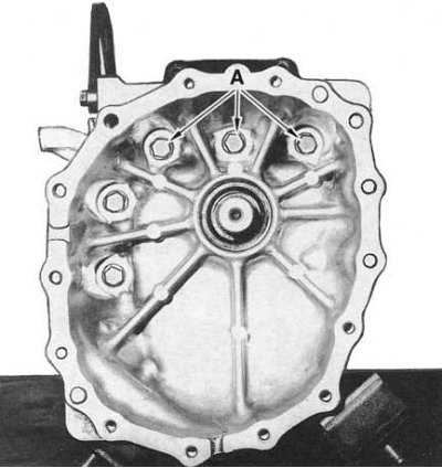
Note. Manufacturers insist that in those shown in the accompanying illustration (A) point, new bolts with locking coating were installed, however, old bolts can also be used by lubricating their threads with Loctite 242 sealant (or its equivalent).
41. Assemble the top cover (see accompanying illustration):
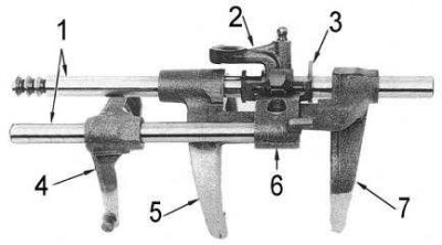
1 - rods; 2 - shock lever; 3 - impact lock; 4 - reverse gear fork; 5 —- shift fork 1/2 gears; 6 - reverse gear lever; 7 —- shift fork 3/4 gears
- Install the reverse gear control assembly and drive the mounting pin into the housing using a hammer and punch.
- Install the 1/2 shift fork, shock lever and 3/4 shift fork into the top cover (observe the order of installation of the components memorized during the dismantling process). Insert the shift rod.
- Install the reverse gear fork and the shift lever into the top cover (follow the correct order of component installation).
- Align the selections in the shift forks, reverse gear lever, shock detent and shock lever. Make sure the striker is positioned between the ribs in the shroud (see accompanying illustration), then install new mounting pins.
1 - impact lock
2 - ribs
- Lubricate the end caps of the selector rods with Loctite 587 (or its equivalent) and install the plugs in the casing.
- Lubricate the fixing ball and guide and install the latter in place, insert the ball and spring into the casing of the top cover. Lubricate the plug and threads of the reversing light sensor-switch with sealant and screw them firmly into the casing.
- Install the selector bracket and lever into the selector housing, insert the selector rod. Fit new roll pins into the selector bracket and lever. Lubricate with Loctite 587 (or its equivalent) new plugs and install them in the selector housing.
- Install the guide plate, making sure that it is turned with a circular groove forward along the selector housing (as noted during the dismantling). Tighten the fixing bolts firmly.
- Lubricate the fixing plungers and balls and install them together with the springs in the selector housing in accordance with the instruction drawn up during the dismantling process). Lubricate with Loctite 587 (or its equivalent) plugs and tighten them firmly.
- Install the selector cover to the top cover (don't forget to replace the gasket) and tighten the mounting bolts to the required torque.
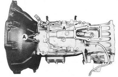
Note. Manufacturers insist that in those shown in the accompanying illustration (A) point, new bolts with locking coating were installed, however, old bolts can also be used by lubricating their threads with Loctite 242 sealant (or its equivalent).
- After replacing the gasket, install the top cover assembly on the transmission, tighten the mounting bolts to the required torque.
42. Assemble the shift lever control cover:
- Install the rubber seat on the lever;
- Lubricate the socket and bushing at the end of the shift lever and insert the lever into the socket, securing it with a new circlip.
- Install the spring and lever in the casing, secure with a new retaining ring.
- Slide the protective rubber boot over the casing (label F forward on the casing). Install the mounting clamps.
43. Temporarily install the gearshift lever on the transmission and, turning the input shaft, make sure that the transmission rotates freely in any position of the lever.
44. When assembling the transmission of models 4.2, consider the differences in it (see Sections Disassembly and general information).