


Note: When disassembling, try to remember the installation position of all removed components. This should simplify subsequent assembly.
1. Remove the transmission from the vehicle. Clean the outer surfaces of the assembly, being careful not to get any solvent into the clutch release bearing.
2. Loosen the mounting bolts and remove the clutch dome, release lever and release bearing assembly from the transmission.
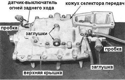
3. Loosen the mounting bolts and remove the upper cover with gasket from the transmission housing (see accompanying illustration).
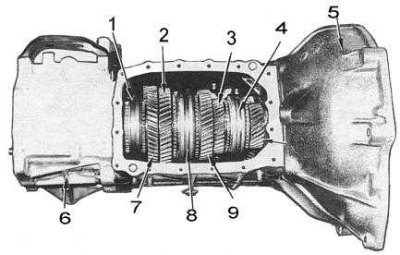
1 - synchronizer clutch; 2 - 1st gear pinion; 3 - 3rd gear pinion; 4 - synchronizer clutch; 5 - clutch dome; 6 - extension casing; 7 - reverse gear pinion; 8 - synchronizer clutch; 9 - 2nd gear pinion
4. Loosen the mounting screws and use a soft-faced hammer to remove the extension housing from the transmission housing (see accompanying illustration). Remove the seal from the casing and discard it.
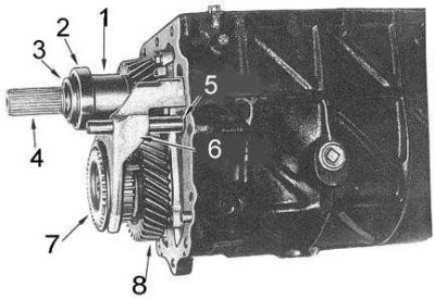
1 - spacer sleeve; 2 - bearing; 3 - holder; 4 - driven shaft; 5 - retaining ring; 6 - shift fork; 7 - synchronizer cone; 8 - intermediate shaft fifth gear pinion
5. Remove the snap ring, retainer and C-rings from the end of the driven shaft.
6. Using a blade-type feeler gauge, measure the clearance behind the intermediate shaft fifth gear. If the axial clearance is outside the permissible limits (see size and adjustment tables at the end of the manual), check the fifth gear components carefully (after disassembling the gearbox) for signs of wear.
The components of the intermediate shaft are shown in the accompanying illustration.
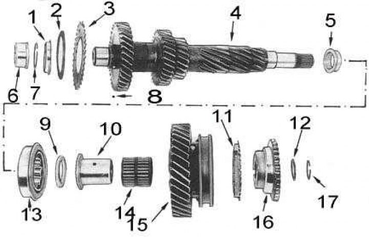
1 - holder; 2 - disc spring; 3 - toothed ring; 4 - intermediate shaft; 5 - inner ring; 6 - inner ring; 7 - retaining ring; 8 - ball; 9 - thrust washer; 10 - coupling; 11 - synchronizer locking ring; 12 - washer; 13 - outer ring; 14 - bearing; 15 - 5th gear pinion; 16 - synchronizer cone; 17 - retaining ring
7. Remove the retaining ring and washer from the intermediate shaft.
8. Remove the reverse gear intermediate shaft lock plate.
9. Engage two gears simultaneously to prevent the intermediate shaft from turning and install a two-jaw puller with its legs behind the fifth gear pinion. Remove the synchronizer cone, fifth gear pinion, synchronizer assembly, shift fork and rod assembly. Remove the roller bearing from the fifth gear coupling.
Note: To avoid damaging the fifth gear teeth, use a wide jaw puller.
10. Loosen the bolts and remove the bearing holder from the transmission.
11. Using a puller, remove the driven shaft rear bearing, fifth gear and spacer sleeve from the driven shaft. If necessary, pull the driven shaft back by hand to facilitate installation of the puller.
12. Install the bearing separator behind the fifth gear roller bearing sleeve, tighten the bolts securely. Using a puller, remove the bearing sleeve from the intermediate shaft (see accompanying illustration) and remove the thrust washer, remembering the installation position of the latter.
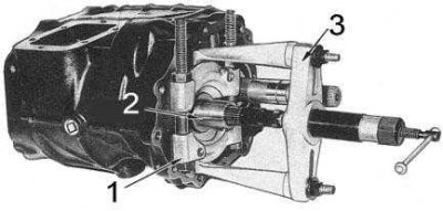
1 - bearing separator
2 — coupling
3 - puller
13. Install the reverse intermediate shaft retaining plate and mounting bolt.
14. Using a puller, remove the driven shaft bearing. It should be firmly secured behind the retaining ring of the outer bearing race. When removing the bearing, use a wooden block as a stop.
15. Loosen the mounting bolts and remove the front cover with the gasket from the transmission. Remove the oil seal from the cover and discard it along with the gasket.
16. Lightly tap the rear end of the intermediate shaft with a soft-faced hammer and use a rotary-translational motion to remove the outer race of the intermediate shaft front bearing from the transmission housing.
17. Lightly tap the front end of the intermediate shaft with a soft-faced hammer, remove the outer race of the rear bearing and lower the intermediate shaft to the bottom of the transmission housing.
Note: You may need a puller to remove the intermediate shaft rear bearing outer race.
18. Turn the primary shaft so that one of the flats of its synchronizer gear turns towards the hole in the upper cover. Remove the primary shaft with the bearing from the transmission housing.
19. Remove the guide bearing and synchronizer locking ring from the front end of the driven shaft.
20. Remove the driven shaft assembly and intermediate shaft from the transmission case through the opening in the top cover.
External view of the driven shaft assembly
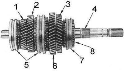
1 - 3rd gear pinion; 2 - 2nd gear pinion; 3 - reverse gear pinion; 4 - driven shaft; 5 - synchronizer clutches; 6 - 1st gear pinion; 7 - synchronizer clutch
21. Loosen the mounting bolt and remove the lock plate of the reverse intermediate shaft. Note the installation direction of the reverse intermediate gear and remove the shaft, gear, thrust washers and roller bearings from the transmission case.
22. Remove the retaining ring and the spacer ring securing the bearing on the input shaft (see accompanying illustration), using a press equipped with support plates, remove the bearing.
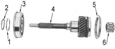
1 - distance ring; 2 - retaining ring; 3 - bearing; 4 - primary shaft; 5 - synchronizer locking ring; 6 - guide bearing
23. Using a blade-type feeler gauge, measure the axial clearance of the first, second and reverse gears on the driven shaft. Record the measurement results.
24. To measure the axial play of the third gear pinion, clamp the bearing separator onto it and securely attach the dial gauge to the separator so that its plunger rests against the end of the shaft (see accompanying illustration). Move the gear back and forth and record the instrument reading. If the axial clearance of the gear is outside the permissible limits (see size and adjustment tables at the end of the Manual), disassemble the driven shaft into its components and thoroughly check the corresponding gear and its associated components. Replace the defective parts.
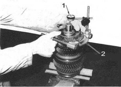
1 - dial gauge
2 — bearing separator
25. Disassemble the driven shaft into components (see accompanying illustration):
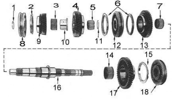
1 - retaining ring; 2 - synchronizer locking ring; 3 - bearing; 4 - 2nd gear pinion; 5 - bearing; 6 - blocking rings; 7 - bearing; 8 - synchronizer assembly; 9 - 3rd gear pinion; 10 - coupling; 11 - retaining ring; 12 - synchronizer assembly; 13 - 1st gear pinion; 14 - bearing; 15 - blocking ring; 16 - driven shaft; 17 - reverse gear pinion; 18 - Synchronizer assembly
- Remove the retaining ring from the front end of the driven shaft.
- Install the bearing separator behind the third gear pinion and remove it using a press with support plates, then remove the 3/4 synchronizer assembly and roller bearing from the shaft. Note the installation direction of the synchronizer hub.
- Position the separator behind the second gear pinion and use a press to remove the pinion, roller bearing and bearing sleeve from the shaft.
- Remove the retaining ring from the 1/2 gear synchronizer hub shaft.
- Place the driven shaft in a press with support plates, using the latter to support the first gear pinion, and remove the 1/2 gear synchronizer assembly, first gear pinion and roller bearing from the shaft.
- Turn the driven shaft over and support the reverse gear pinion on the support plates. Remembering the installation positions of the components, remove the reverse gear pinion, synchronizer assembly and roller bearing from the shaft.
26. Disassemble the intermediate shaft assembly into components (see illustration):
- Using a press with support plates, remove the inner races of the front and rear bearings from the intermediate shaft.
- Remove the retaining ring, retainer, disc spring, toothed ring and ball from the front end of the shaft.
27. If necessary, disassemble the top cover into components (see accompanying illustration):
The original is posted on the portal (nissanbook.ru)
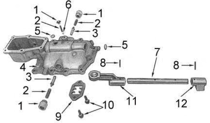
1 - plug; 2 - spring; 3 - plunger; 4 - casing; 5 - cork; 6 - ball; 7 - gear selection rod; 8 - pin; 9 - plate; 10 - bolts; 11 - selector rod lever; 12 - selection rod bracket
- Loosen the mounting bolts and separate the gear selector housing from the upper cover. The components of the gear selector housing are shown in the accompanying illustration.
- Remove the limiting plug from the top of the selector housing, remove the spring and ball. Remove the remaining plugs and remove the springs and plungers, noting the installation position of each component.
- Using a drift, remove the pin securing the selector bracket to the gear selector shaft.
- Turn the selector housing over, loosen the mounting bolts and remove the guide plate. Remember the installation positions of the bolts.
- Use a drift to knock out the pin securing the lever to the gear selector shaft while simultaneously removing the spherical plug from the housing. Knock the gear selector shaft forward out of the selector housing. Locate the selector bracket and front plug.
- Unscrew the plug and remove the retaining spring, guide and ball from the top cover.
- Remove the reverse light switch sensor.
- Using a hammer and screwdriver, remove and discard the gear selector shaft plugs.
- Remove the mounting pins of the reverse gear fork and the reverse gear selector lever. Remove the reverse gear selector rod, then remove the fork and lever, noting their installation positions. The upper cover with the selector cover removed is shown in the accompanying illustration.
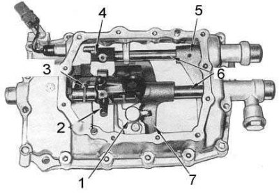
1 - reverse gear control assembly; 2 - impact lever; 3 - impact lock; 4 - reverse gear selection lever; 5 - reverse gear engagement fork; 6 - gear selection rods; 7 - 3/4 gear shift fork
- Remove the striker lever mounting pin, remove the selector rod, and then, while remembering the installation position of the components, remove the striker lever, striker retainer, and shift forks from the top cover. The internal components of the top cover are shown in the accompanying illustration.
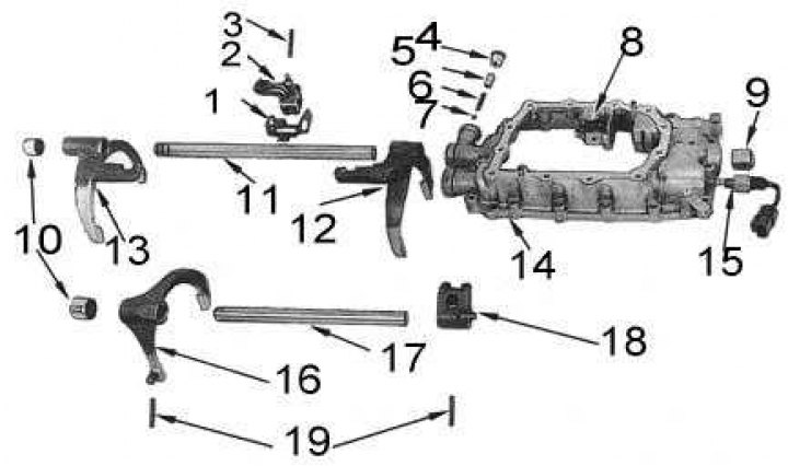
1 - impact lock; 2 - impact lever; 3 - pin; 4 - plug; 5 - guide; 6 - spring; 7 - ball; 8 - reverse gear control assembly; 9 - cork; 10 - traffic jams; 11 - rod; 12 - 3/4 gear shift fork; 13 - 1/2 gear shift fork; 14 - lid; 15 - Reverse light switch sensor; 16 - Reverse gear engagement fork; 17 - rod; 18 - reverse gear engagement lever; 19 - pins
- Remove the retaining pin and remove the reverse gear control assembly.
28. If necessary, disassemble the gear shift lever control housing:
- Remove the clamps and slide the rubber protective cover up the lever.
- Remove the large retaining ring and remove the gear shift lever with the spring from the housing.
- Remove the retaining ring, pull the shift lever out of the socket and remove the rubber seat from it (see accompanying illustration).
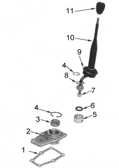
1 - gasket; 2 - casing; 3 - spring; 4 - retaining ring; 5 - nest; 6 - saddle; 7 - bushing; 8 - washer; 9 - protective cover; 10 - gear shift lever; 11 - handle